
Cost-Effective Data Acquisition System For A Vibration Test System
August 15, 2023
Story
Modern spacecraft and aircraft are highly complex technical systems in which many elements may not be optimal in terms of design and structural strength.
Typically, the design of these objects requires minimizing weight and size. Furthermore, it is common for spacecraft to require deployable systems, such as antennas or solar panels. As a result, their structure becomes responsive to external disturbances and much less rigid. The variety of external forces and environmental factors affecting these vehicles at all stages of their operations, for example, during the launching of a rocket or its orbiting, is accompanied by many transient processes in their structure. These processes result in the emergence of internal stresses and deformations in various sections of the structure. It is not difficult to imagine the scale and catastrophic consequences of a structural defect not detected in time.
Hence, in the development process, it is necessary to obtain confirmation of the strength and operational capability of the structures of spacecraft and aircraft at all stages of operation. Lengthy strength tests accompany the completion of the development and manufacture of the apparatus by simulating external mechanical and vibrational impacts using special equipment. Testing is conducted to detect structural defects, the ability to withstand various external influences and to evaluate the qualitative properties and quantitative values of products at stages of development, production, and operation. The primary information on tests for external factors and the degree of their severity is described in various industry standards. For example, SMC-S-016 (2014) Test Requirements for Launch, Upper-Stage, and Space Vehicles describes the requirements for testing launch vehicles, booster units, and spacecraft.
Vibration Test Systems
The product testing for mechanical factors includes vibrations, shocks (single and multiple), linear acceleration, and acoustic noise. The whole apparatus can be tested on specialized electro-hydraulic vibration stands, while individual components are tested on less powerful stands based on electrodynamic vibrators. Vibration systems can reproduce all signal forms described in the standard mentioned above. The level of test hardness is determined by the parameters of the vibration system, which include three components: frequency range, vibration amplitude, and duration of exposure.

Fig. 1. Simple vibration test system
The simple vibration test system (Fig.1) operates as follows: The test object is mounted on the shaker using a special fixture. Control software installed on a computer generates commands according to the test profile specified by the user. These commands are sent to the vibration controller, which generates control signals for the shaker to produce a periodic or random vibration effect on the test object. The role of the power amplifier is to provide driving current to the vibration generator, converting the small electrical signal generated by the controller. A control accelerometer placed on a shaker platform measures the parameters of the vibration (acceleration, displacement etc.) and provides feedback to the controller, allowing for error correction in the shaker control signals. Throughout the testing process, the software continuously monitors and displays all relevant data.

Fig. 2. Vibration test system with Data Acquisition System
In some cases, such as for detecting resonances of particular elements in a structure, measurement accelerometers are installed directly on the object being tested. The more complex and larger the structure, the more sensors need to be installed on the test object. This ensures the completeness and reliability of the test. Complex vibration test systems with a large number of measurement channels require a separate data acquisition and processing system connected to a computer (Fig.2). Depending on the functional capabilities of the vibration test bench, the data acquisition system can independently perform measurements and analysis, and also can completely replace the vibration test system controller.
One of the most popular data acquisition systems for complex testing rigs is LMS SCADAS (now called Simcenter SCADAS) produced by Siemens company (Fig. 3).

Fig. 3. Siemens LMS SCADAS Lab data acquisition system
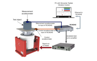
This data acquisition system can also be used for conducting complex vibration and shock tests (Fig.4).

Fig. 4. Vibration test system based on LMS SCADAS
The LMS SCADAS system offers extensive functionality for various applications and a range of interchangeable modules for measuring different physical quantities. It also includes specialized software Simcenter Testlab for analyzing test data. However, despite these advantages, the LMS SCADAS data acquisition and analysis system has a significant drawback - cost. Expanding its capabilities, such as increasing the number of input channels or adding signal processing directly within the device (mathematical operations, digital processing using user-defined algorithms), can also be quite expensive.
Custom Data Acquisition System
Back in 2017, we encountered an interesting and non-trivial challenge. Our task was to develop a proprietary data acquisition system for a large vibration testing platform for the aerospace industry. The system needed technical specifications comparable to LMS SCADAS, with more input and output channels and the ability to perform mathematical processing of digitized signals, but at a significantly lower cost. Furthermore, the system needed to seamlessly integrate into the existing data acquisition and analysis infrastructure, serving as an expansion to its capabilities.
According to the technical requirements, the developed system had to fulfill the following functions:
- receiving analog signals from 78 measurement inputs of three-axis ICP force sensors, specifically the 261A03 model from PCB Piezotronics;
- reproduction of dynamic components of sensor signals and transmission to external equipment for further processing by the LMS SCADAS vibration test control system;
- mathematical processing of input signals, specifically the calculation of moments of a force based on instantaneous force values;
- formation of 32 aggregate signals, where the instantaneous values correspond to the calculated functions of the instantaneous values of the signals at the measuring inputs.
From a design perspective, we did not seek out any technically complex solutions and instead opted for ready-made, standardized chassis for a 6U 19-inch rack from Shroff (Fig.5). The data acquisition system itself was implemented following a modular principle and consisted of 13 ADC modules, 4 DAC modules, and a control CPU module.
 |
Fig. 5.Case design for custom Data Acquisition System.
All modules were connected to slots located on the motherboard, with each slot having its unique address, hard-coded by a binary code on dedicated connector pins. Inter-module data exchange was performed via high-speed differential buses implemented on the M-LVDS interface.
Each ADC module (Fig. 6) had six analog signal inputs (BNC connectors). All inputs had overvoltage protection, amplifiers, and anti-aliasing filters. For signal conversion, two 6-channel ADS8556IPMR ADCs were used in parallel due to time constraints, but only three channels from each ADC. Control and data acquisition from the ADCs were performed by STM32F745 microcontroller through digital isolators Si8660BA-B-IS1. For data exchange with the CPU module, each module was equipped with an M-LVDS driver connected to an individual driver on the CPU module through the motherboard. The digital and analog parts of the module were electrically isolated from each other, and two separate power supplies were used to power these parts on all modules. This approach resulted in significant cost savings, eliminating the need to implement expensive isolated power sources on each module, such as the uModule LTM8057 from Analog Devices. Although this solution had its drawbacks, as it did not achieve complete isolation between the channels, it was unnecessary for this particular task.

Fig. 6. Block diagram of the ADC module.
To calibrate and monitor the functionality of the channels, we installed relays that, when triggered by the microcontroller, disconnected the external circuits from the ADC inputs and connected them to a control signal. To improve cost-effectiveness, we did not implement a separate control signal generator but instead utilized one of the channels of the DAC module (see below) that could be switched through the relays. We also implemented the option to bypass the low-pass filter. This was necessary to minimize signal processing delay across the entire system.
The DAC module (Fig. 7) was designed to generate aggregate output signals and had eight channels equipped with protection circuits. Similar to the ADC module, it was connected to the data bus through the M-LVDS interface for data exchange with the CPU module. The output signals were generated using two DAC chips DAC7742YB/250 controlled from the microcontroller STM32F745 through digital isolators Si8660BA-B-IS1. Additionally, there was an option to disable the low-pass filter at the DAC output upon command from the CPU module. Similar to the ADC module, the DAC module had two galvanically isolated power sources connected to it.

Fig. 7. Block diagram of the DAC module.
The CPU module (Fig. 8) performed the functions of generating control commands for the modules, reading data from the ADC modules, writing data to the DAC modules, signal processing, and communicating with external systems. The CPU module had 17 high-speed M-LVDS drivers for individual interaction with each module. The interaction with other modules and signal processing were performed by the Artix 7 FPGA. The STM32F417 microcontroller facilitated communication with external devices via Ethernet and USB interfaces and controlled the operation of the FPGA.

Fig. 8. Block diagram of the CPU module.
The implementation involved precise clock synchronization by the CPU module for conversion, data reception, and data transmission across all other modules. The ADC module triggered conversions and transmitted the previous conversion result through the high-speed serial data bus using the clock signal. Simultaneously, the DAC module received data from the CPU module via the data bus and initiated the conversion of the received data from the previous clock cycle. As a result, the total signal transmission delay from the ADC module inputs to the DAC module outputs, without considering processing, was only four clock cycles. An additional four clock cycles were allocated for signal processing. Thus, the total signal delay in the data acquisition system amounted to 8 clock cycles, which, at a frequency of 16 kHz, was only 500 microseconds.
All modules were connected to the motherboard (Fig. 9), which was installed at the base of the chassis, using edge connectors. The motherboard had 18 slots dedicated to the ADC, DAC, and CPU modules. Its primary purpose was to integrate the modules through data buses, address lines, and clock signals and provide power supply to each module's analog and digital parts.
The system was powered by several galvanically isolated power supplies located on the rear side of the chassis. Bipolar power supplies with voltages of ±24V were used to power the analog subsystems, including the ADC and DAC.

Fig. 9. Block diagram of the motherboard and power supplies.
Summary
As a result, the cost of our system turned out to be comparable in price to only one eight-channel universal module VB8 from LMS SCADAS. And taking into account the expenses for the entire development and assembly cycle, the product's final cost did not exceed the cost of five similar modules. Moreover, regarding technical specifications (sampling frequency, dynamic range, accuracy), it was slightly better.

Fig. 10. The Data Acquisition System connected to a signal generator and an oscilloscope
The developed system has also performed exceptionally well in operation over the past four years, without any complaints from the customer.
In our future plans, we aim to expand the functionality of the existing system by adding radio network modules for wireless interaction with sensors. We also plan to redesign the ADC, DAC, and CPU modules to further reduce costs and improve performance.
Petr Liutik has over a decade of experience developing software for various Embedded Systems. He started his career by working on wireless fire alarm systems and intelligent home systems based on 802.15.4 and ZigBee technologies. Later, he engaged in software development for a Programmable Logic Controller running on the QNX operating system and implemented CODESYS support. Petr also participated in porting and developing the Linux-based mobile operating system Aurora/Sailfish. Currently, he is involved in developing a distributed file system for Linux and FreeBSD operating systems.
Konstantin Liutik is an experienced engineer with a strong background in analog and digital electronics, circuits and PCB design. He has expertise in developing low-power microwave transmitters, receivers and antenna switches. Additionally, he has experience designing high-speed multilayer PCB topologies using Mentor Graphics CAD and signal integrity analysis tools such as HyperLynx. Throughout his career, Konstantin has successfully developed numerous projects based on Xilinx and Altera FPGAs using hardware description languages like Verilog and VHDL.

Petr Liutik has over a decade of experience developing software for various Embedded Systems. He started his career by working on wireless fire alarm systems and intelligent home systems based on 802.15.4 and ZigBee technologies. Later, he engaged in software development for a Programmable Logic Controller running on the QNX operating system and implemented CODESYS support. Petr also participated in porting and developing the Linux-based mobile operating system Aurora/Sailfish.
Konstantin Liutik is an experienced engineer with a strong background in analog and digital electronics, circuits and PCB design. He has expertise in developing low-power microwave transmitters, receivers and antenna switches. Additionally, he has experience designing high-speed multilayer PCB topologies using Mentor Graphics CAD and signal integrity analysis tools such as HyperLynx.


