For the Professional Maker: ClearCrawler Moves with the Help of Capacitors and nRF24L01+ Control
August 05, 2019
Blog

After considering the beauty and unreliability of the Clearwalker, along with the rather basic but reliable design of the StrandMaus, I decided to combine the two into the ?ClearCrawler.?
Three years ago, I wrote an article here entitled “Many attempts before DIY perfection,” referencing how it took me four attempts to make a little “StrandMaus” 8-legged walking creature that worked with any sort of consistency. While I’ve been happy with its performance, and it still (hopefully) walks after being shown at several events, I’ve since iterated on this to create several more versions. These include the ClearWalker, which was made out of clear polycarbonate, and walked inconsistently for a short amount of time, and a rocket launcher Strandbeest made from a heavily modified kit.
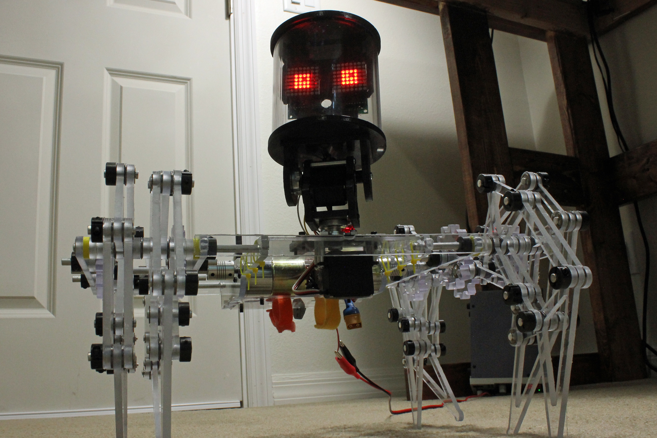
In each instance, I learned new lessons, and after considering the beauty and unreliability of the Clearwalker, along with the rather basic but reliable design of the StrandMaus, I decided to combine the two into something that I now call the “ClearCrawler.” The device uses a lightly modified version of the StrandMaus body, but instead of MDF (manufactured wood), the frame is built with polycarbonate that was mostly left over from the ClearWalker.
While there wasn’t much different here mechanically, I also wanted to revise the control system to something I could expand upon later, i.e. an Arduino dev board with a motor driver. With the Strandmaus version, I used a relay-based h-bridge controller, and all RC components. This worked OK, the design seemed to be a bit of a dead end.
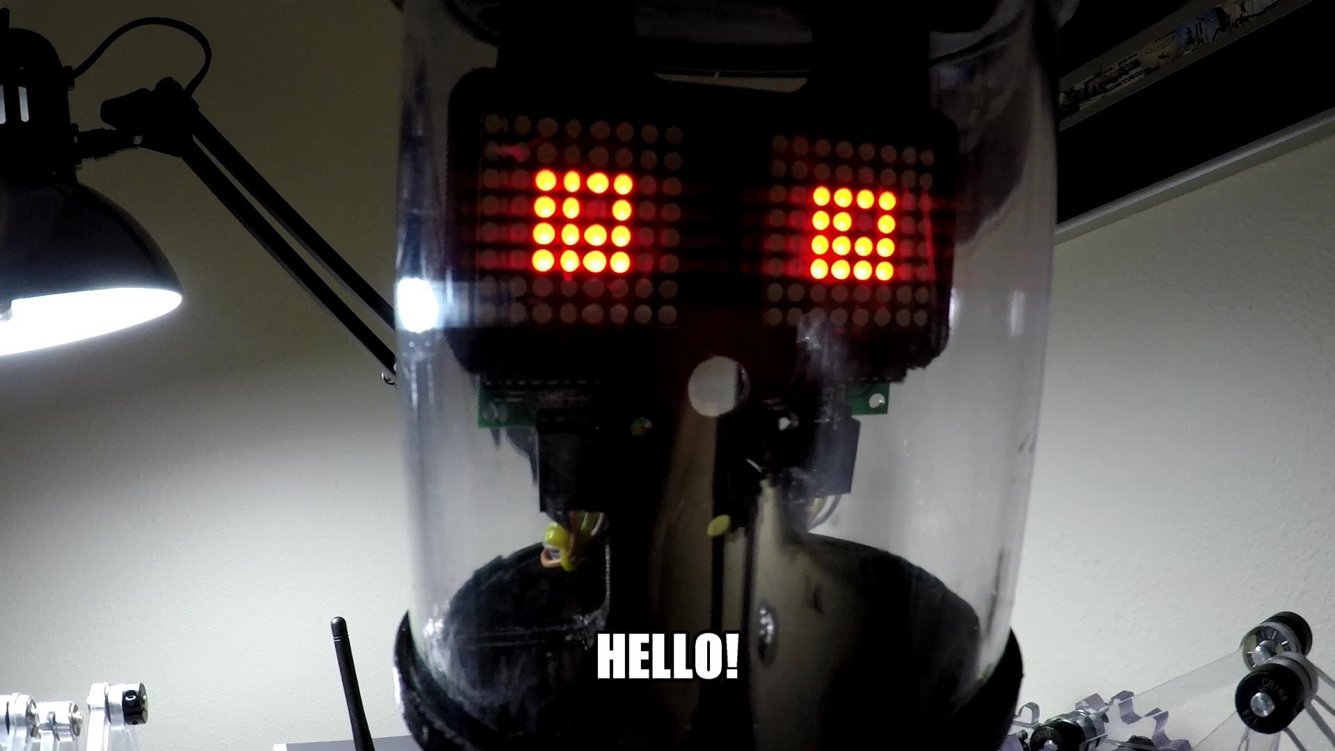
Control for the ClearCrawler is based on the Arduino Nano with an I/O expansion board, allowing me to plug in a variety of servos and outputs in a way that would be difficult on a breadboard. This setup also means the possibility of automated control or functions in the future if I decide to go that route. Current Outputs include forward and backward directional outputs for two motors, two PWM outputs for a pan/tilt head mechanism, a pair of MAX7219 8x8 LED matrices, and a small speaker.
RF Problems
Input to the device is via an Arduino Uno and joystick shield, which was shoddily put together with zip-ties and a lipstick-style battery. While a bit rough-and-ready, it actually works pretty well. The most frustrating struggle here was getting the popular nRF24L01+ modules to communicate. While I could get them to work sometimes when directly wired to the correct pins on my Arduino boards, when connected to their respective shields, the purportedly RF-enabled Nano and Uno boards didn’t work properly.

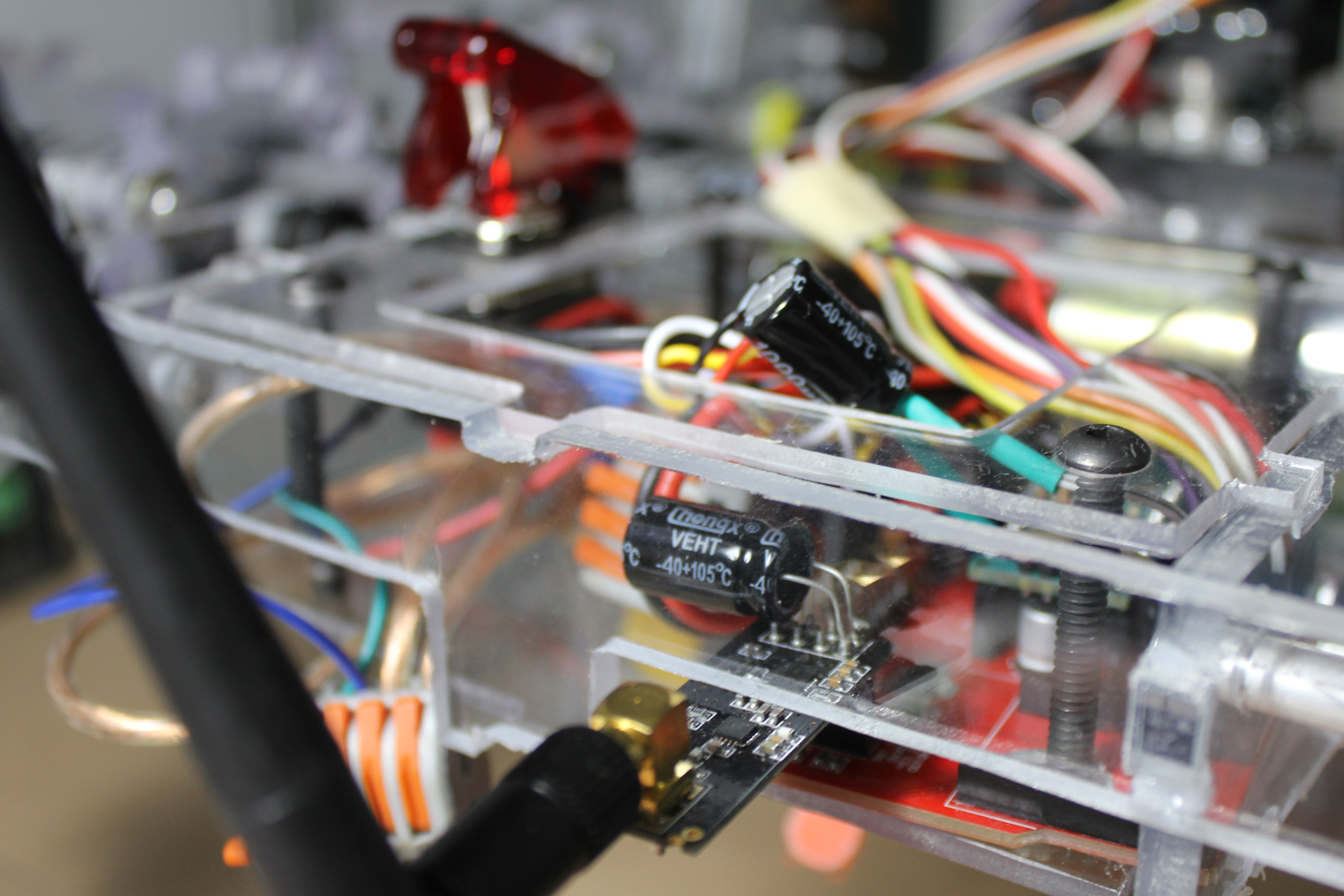
The first issue was that the Nano I/O shield apparently only works with the RF module properly when connected via the barrel jack, not when powered by the Nano’s USB connector. It took me longer than I’d like to admit to figure this out, and I even considered using the RF-Nano seen here, but once properly plugged in, the larger power issue was solved. The other issue—inconsistent power—was solved with the addition of a 10 microfarad (μF) capacitor across the power and ground lines on the transmitting module. A 1000μF cap was used on the receiver, which was certainly overkill. These relatively simple solutions cost me hours of work, so don’t make the same mistake when dealing with these modules.
In addition to the RF caps, I added a 1000μF capacitor to a 5V power and ground pin on the I/O shield in order to stabilize the power supply, especially useful when feeding the two servos. While using a more powerful 5V supply would likely have been a better practice here, perhaps you might say that a liberal usage of capacitors can—at least partially—atone for poor electronics designs. I’m going to pin that as the big lesson from this build. That, and the fact that using lots of thrust bearings in complicated mechanical builds (88 used here) is a good idea but may end up demolishing your budget in the process.
So far, I’ve had it walking successfully during a day-long Maker Faire with only a few very minor issues, which I’d call a success. As with any project though, “perfection” is a very relative term, and I hope to make this “platform” even better over time!
Jeremy S. Cook is a freelance tech journalist and engineering consultant with over 10 years of factory automation experience. An avid maker and experimenter, you can follow him on Twitter, or see his electromechanical exploits on the Jeremy S. Cook YouTube Channel!