MPU Security Part 3: Partition Problems and Solutions
May 03, 2019
Blog

This is the third part of a four-part series of articles presenting a unique product MPU Plus? and a methodology for using the Cortex-M MPU to achieve improved MCU security.
This is the third part of a four-part series of articles presenting a unique product MPU‑Plus® and a methodology for using the Cortex-M Memory Protection Unit (MPU) to achieve improved Microcontroller Unit (MCU) security. Part 2 presented partitioning, secure boot, MPU control, and system calls. Part 1 presented some introductory concepts: MMUs vs MPUs, increasing need for security, protection goals, MPU-Plus snapshot, Cortex‑v7M and v8M, and MPU operation.
Partition Problems
Defining partitions is but one step in the security process. We must also be concerned about what a hacker will do after he penetrates a partition. In this regard, four major problem areas emerge:
- Heap usage.
- Function call APIs.
- Interrupts.
- Task creation and control.
There are others, but these will do for now. Solutions are discussed in what follows.
Heaps
Especially with object-oriented languages, using heaps in modern application code is popular. This is a growing trend as embedded systems become more complex and are expected to do more operations – especially in IoT systems. Also, some middleware uses heaps.
It is obviously unacceptable for utasks to have direct access to the main heap. A hacker could easily bring down the whole system simply by exhausting or corrupting it. Hence, dedicated heaps must be used in umode partitions, and possibly pmode partitions, that require heaps. To solve this problem, eheap™ has recently been upgraded to support multiple heaps. These heaps will generally be small, but not necessarily so. Given its proclivity for small heap support, this is a good solution. For more information see:
eheap User's Guide, by Ralph Moore, Micro Digital, Inc.
Figure 6 illustrates allocating a small dedicated heap from the main heap. Heap calls from TaskA operate only on this heap and cannot go outside of it. TaskA can access the main heap only for a protected block or a protected message, as shown by the dashed line, and cannot go outside of the protected block. (Protected blocks and messages are discussed later.) Hence the main heap is protected from TaskA, which may be a utask or a ptask.
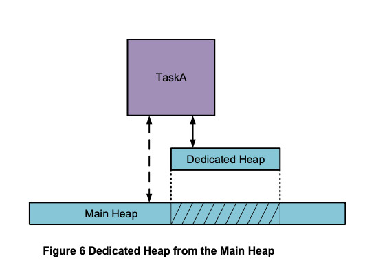
Memory for a dedicated heap could also be a static block of memory allocated by the linker.
Function Call APIs
Function calls are the predominant API between sections of software. This creates a problem. For example, an application partition may need file system services. As a consequence, the file system API functions must be accessible to it. Subroutines in the file system must be accessible to the file system API functions and driver functions must be accessible to the subroutines. Also, file buffers and global variables must be accessible to all of these functions. So, the whole ball of wax – file system and driver(s) – ends up in a code region of the application partition, and file buffers and globals end up in a data region of the application partition. Worse, if other partitions need file I/O then these regions become common regions between those partitions.
If a hacker penetrates one of the partitions, he has access to the other partitions via the common regions. Although he cannot necessarily control those partitions, he can certainly bring them down and possibly disrupt the whole system. The solution to this problem is partition portals, which are discussed in Part 4.
Interrupts
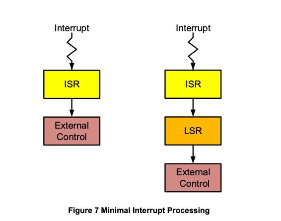
Interrupts cause an immediate switch to pmode and thus expose pmode to the outside. Recalling that any pmode function is but one step away from opening the Vault, this is a serious security problem. In many cases, as illustrated in Figure 7, only a few lines of carefully written code in an ISR or in an ISR + LSR are necessary. (LSRs provide deferred interrupt processing.)
Unfortunately, the limited number of MPU slots aggravates the interrupt problem. Initially, we defined a sys_code region to contain ISRs and other system code needed by interrupts and a sys_data region for needed data. The Vault, Security, and other sensitive partitions were excluded from these regions. sys_code and sys_data were present in every task MPA. Hence, when an interrupt occurred, ISRs and LSRs could run, but had limited access to other pcode and pdata. This is still our preferred solution, if the MPU has enough slots.
The sys_code and sys_data regions were privileged regions and thus not usable by utasks. Unfortunately, we found that for 8-slot MPUs we could not afford to waste two slots for every utask. Hence, standard MPU-Plus turns on Background Region (BR) whenever switching to a utask. BR has no effect in umode, but when an interrupt occurs it allows the ISR and LSR to run. Unfortunately, BR on in pmode also allows accessing everything – hence the Vault is open!
Where practical, it is recommended that ISRs immediately load minimal sys_code and sys_data regions into the MPU and switch BR off. This at least closes the vault and makes accessing it a little more difficult. When exiting, the ISRs must, of course, restore the replaced regions.
For ptasks, the sys_code and sys_data regions are present and usable. They are somewhat enlarged to include other system functions. Hence, the two regions do not pose a problem and BR is turned off whenever a ptask runs in order to protect the Vault, among other things.
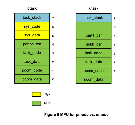
Figure 8 illustrates the approach adopted. Note the sys_code and sys_data regions for the ptask. The utask does not have these regions because BR is on, instead. As a consequence, it has been possible to expand the utask MPA by two slots. This has enabled splitting the peripheral region in MPU slot 4 into separate USB host and UART1 regions in slots 4 and 5, respectively. This provides better security because there are several peripherals in memory between the USB host and UART1, which are now excluded from access by the utask. Also slot 6 is available for a dynamic region (see Part 4). Note that for both tasks, there are task code and task data regions and common code and common data regions. The latter regions are not the same for the ptask and the utask – even if the ptask eventually becomes the utask.
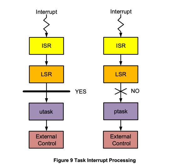
When more than minimal interrupt processing is required, Figure 9 illustrates what to do on the left and what not to do on the right. The objective is to move as much processing as possible into a utask where hacking can be better contained. Here, as for simple interrupts, the goal is minimal code in ISRs and LSRs. Also, this code must be carefully written -- it must employ extensive range checks and other tests intended to defeat hacking. This is challenging if high performance is also required.
Despite the foregoing caution, it may be necessary to do full interrupt processing in pmode (i.e. the right-hand side of Figure 9). This is definitely faster and simpler, especially if there are critical sections of code and if system services are being called. In this case, it is preferable to do the processing in the ptask rather than the ISR or LSR since a ptask offers more protection, since BR is disabled, so it is restricted to the MPU regions.
More Interrupt Problems
Interrupt problems just won't go away. Another set of problems revolves around disabling and enabling interrupts. In umode these two operations are no-ops. So, if interrupts are being disabled to protect a critical section in your umode code, guess what? They aren't disabled and you have a hidden problem! This can be a headache when converting legacy code to ucode, since interrupt disabling is commonly used to protect critical sections of code. It is just as well that interrupts cannot be disabled from umode. If they could, it would be a field day for hackers. Note that this is not a problem in pmode since all privileged instructions can be accessed in pmode.
The solution to this problem is to allow specific interrupts to be masked and unmasked by utasks, using the smx functions sb_IRQMask(irq_num) and sb_IRQUnmask(irq_num). The range of IRQs that a task is allowed to mask and unmask is stored in its TCB. Hence, damage that can be done by a hacker is limited only to interrupts that are used by the task. For legacy code, it is necessary to track down all places that interrupts are disabled and enabled, replace them with masking and unmasking, and then load permitted IRQ ranges into the task TCBs.
To help find uses of interrupt disabling and enabling in umode, alternate versions of interrupt disable and enable macros or functions can be used that trap if called in umode. These are helpful to find misuses from macros and wrapper functions or code that was expected to run in pmode.
Task Creation and Control
Clearly a hacker could really cause trouble if he could create, delete, start, and stop tasks from a umode partition that he had penetrated. Hence, task functions should not be permitted in umode. One would think that all task creation and control should be performed only in pmode.
Unfortunately, this does not work well, especially if converting legacy code. To require that all tasks be created during pmode initialization results in unexpected limitations and complexities. In many situations, tasks need to be created as they are needed in order to deal with events as they occur. For example, tasks may be created as USB devices are plugged in and the tasks may be deleted when the USB devices are unplugged. As another example, some USB controllers can be switched between host and device modes, thus requiring one USB stack to be disabled and the other to be enabled. To save resources, this is likely to be implemented by deleting one set of tasks and creating another set of tasks.
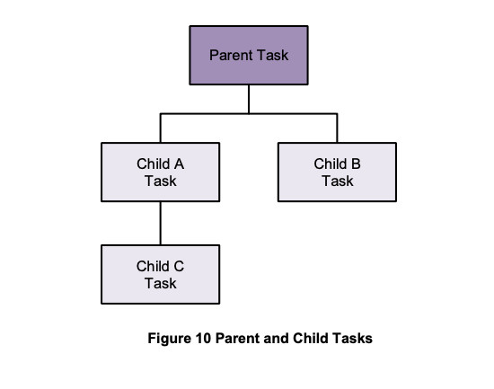
The solution to this problem is task families, as shown in Figure 10. Typically, a partition will have one parent or root task, which is created in pmode and which runs in pmode to perform certain partition initializations. The latter may include creating or spawning some child tasks. The parent task then switches itself into umode, where it can start its child utasks and possibly create and start others. This provides the necessary flexibility for dynamic task control. Figure 8 illustrates a task family. Note that child tasks can create other child tasks and thus become parents for those children.
A parent task can create, start, stop, delete and perform other functions on its child tasks. It cannot perform these task functions on its parent or siblings, nor on their children. In addition to this limitation, a child inherits its parent's MPA template and all other parent limitations. Hence a child cannot do anything that its parent cannot do. (Otherwise, a hacker could breed monsters.)
Task Local Storage (TLS)
The task create function allows creating a TLS area that follows the Register Save Area (RSA) that follows the task stack:
TCB_PTR smx_TaskCreate(fun, pri, tlssz_ssz, fl_hn, name)
tlssz_ssz is a split parameter: the upper 16 bits define the TLS size, tlssz, and the lower 16 bits define the stack size, ssz. Both can be up to 64 KB. TLS is available only if ssz > 0 – i.e. the task stack must be a permanent stack from heap, hn. TLS is a bonus protected task data block that does not cost an additional MPU region. It can be used in the same manner as a protected data block (see Part 4).
The TLS pointer is stored in the TCB of the task. It can be accessed as follows:
dp = (u8*)smx_TaskPeek(ut2a, SMX_PK_TLSP);
This operation is permitted for utasks as well as ptasks. The TLS can contain only structures and arrays (i.e. buffers). If all task static variables are defined as fields of structures and task buffers are defined as arrays, then the TLS can replace the task_data region, as long as no other task is attempting to access any of the variables (if so, put them into the com_data region). This frees up the task data slot to be used for another region in order to create smaller, more secure regions. Figure 8 is a primary example of this benefit.
The next part of this series will discuss dynamic data regions, protected data blocks, task local storage, protected messages, partition portals, debug support, and conclusions. For more information see www.smxrtos.com/mpu.
Ralph Moore is President of Micro Digital. A graduate of Caltech, he has served many roles at Micro Digital since founding it in 1975. Currently he is lead architect and programmer for MPU-Plus, eheap, and smx.