Bus Bars: The 3D Solution to Excessive IR Power-Rail Drop
September 13, 2019
Story

Voltage drop and low voltage at the load is more than just a nuisance. It can cause circuits to not function at all, or function erratically when the voltage is at the edge of the IC specification.
Despite the widespread use of low-power ICs – or counterintuitively, because of it – DC power-rail currents on PC boards keep increasing. It’s not unusual to have a modest-size board drawing high tens of amps and even more. Getting rid of the resultant I2R heat is a well-known thermal problem, but there’s a problem which comes before that consequence: delivering the nominal rail voltage to the load without excessive voltage drop due to PC board track resistance.
This phenomenon is defined by Ohm’s Law, the simplest of equations: V = I × R. The voltage drop is a function only of the current value and the trace resistance. It is independent of the rail voltage, although the percentage loss is obviously far greater with a 1-V rail versus a 15-V rail for a given loss.
Voltage drop and low voltage at the load is more than just a nuisance. It can cause circuits to not function at all (not good), or function erratically when the voltage is at the edge of the allowed specification for the various ICs (which is often worse), as the typical rail tolerance window ranges from ±1 percent to ±5 percent, depending on the component. That’s why it’s critical to analyze the drop between power supply and load, and deal with excessive IR drop.
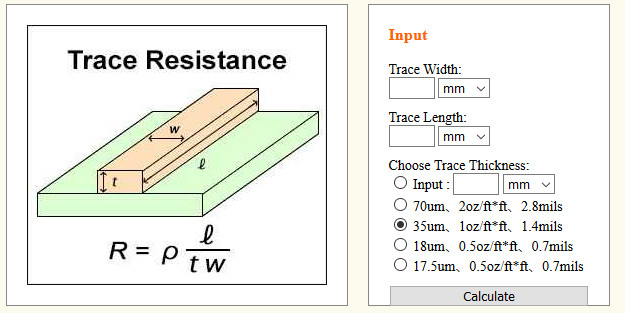
How much drop can be expected? Again, it’s a simple calculation. A PC-board trace, which is 1-mm wide and 10-cm long on standard “1-oz” copper cladding (actually 35 µm thick) will have a resistance of about 50 mΩ (the resistivity of copper is 1.74 × 10⁻⁸ Ω-m at 20°C), Figure 1 (left). At a modest current of 10 A, that’s 500 mV of drop along the supply rail alone – and it may even be twice that if the DC ground-return is via a similar trace rather than a wide ground plane. There are many handy online resistance calculators for this loss, Figure 1 (right) and References 1 to 3; many of them also calculate temperature rise as well.
To address this problem, designers can use thicker, more costly PC board cladding (2 ounce/70 µm is common) but this only cuts the loss in half. Another popular option is to use an intermediate bus converter (IBC) architecture for power distribution, where a higher voltage (and thus lower current) such as 24 VDC or 12/15 VDC is distributed throughout the board, and then locally regulated as needed for the IC or subcircuit close to the IC. This works well technically, but there’s cost in additional DC/DC regulators as well as board real estate.
Fortunately, there’s another potential solution if you think “out of the box,” or at least “out of the plane.” No, it’s not adding additional PC board layers, although that can certainly be done – again, at a cost in board material, layout issues with buried, blind, and through vias (formal name is “vertical interconnect access”), and more.
Instead, it’s the use of “old-fashioned” bus bars (a standard in industrial setting to deliver power to motors and more), but on a much smaller scale suitable for PC boards, even those with tight inter-board spacing in a card cage. The bus bar concept and implementation are simple: it’s an insulated strip of copper with protruding connection pins along the long edge and is available in many standard lengths. Custom lengths are also available at negligible or no up-front NRE (non-recurring engineering) cost and minimal lead-time impact.
The bus bar fits onto the board like any other through-hole component and adds an independent DC rail path. It can be wide and thick enough to provide a current path with milliohm and less resistance. It’s a no-headache, easy add-on to the PC board, which allows another degree of freedom for the layout and distribution of those high-current rails. It also facilitates better, shorter routing, and better signal integrity of signal paths, since the wider DC rail is no longer in the way of the best path.
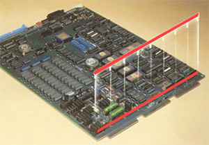
There’s another benefit the bus bar provides. There are dual- and even triple-layer versions so the same bus bar can carry one or more power rails as well as ground. Bus bars also offer a free secondary benefit, as they stiffen the PC board against flexing and vibration, Figure 3, which is a concern as circuit boards get larger.

Bus bars are available in hundreds of standard configurations from dozens of vendors. Before you look for a more complex solution to the problem of lowering IR loss to an acceptable level, such as wider traces, thicker PC board copper, another board layer, or use of an IBC and local DC/DC regulators – all of which have their place in the solutions toolkit – consider the 3D technique and component that literally takes your PC board to another dimension.
References
- MustCalculate
- Bittele Electronics Inc
- Trance-Cat
- Texas Instruments, SLYT23,“Spreadsheet modeling tool helps analyze power- and ground-plane voltage drops to keep core voltages within tolerance”
- Advanced Layout Solutions Ltd, “IR-Drop Analysis”
- OurPCB.com, “PCB Trace-The Importance of PCB Traces In the PCBs”
Related content