The Basic Concept of Digital Power
March 14, 2019
Story

The primary objective of any AC/DC or DC/DC power supply or regulator is to provide a stable DC-output voltage despite changes in input voltage or load conditions.
It wasn’t that long ago that "digital power" was mostly a concept with few commercial installations. Times have changed, and, these supplies are now standard and widely used in power-intensive applications such as data centers. Their attributes make it possible to provide DC rails at hundreds of amps in tight spaces, with high efficiency, and monitored and managed performance.
Power-supply designers are generally a cautious group, as they must be when dealing with high current, voltage and power levels—and the consequences to equipment and people of supply malfunction or failure. While there was some early reluctance to embrace the firmware-based approach of digital power, the situation has changed as they have proven themselves. Their thermal benefits include improved efficiency from low to full load, reduced stress on components, simplified cooling, and increased mean time between failures. They also bring system-level benefits by reporting on their status, trends, and operation in real time, and their ability to adapt and adjust.
What is a digital power supply?
The primary objective of any AC/DC or DC/DC power supply or regulator is to provide a stable DC-output voltage despite changes in input voltage or load conditions. Doing so requires some form of closed-loop control within the DC/DC converter, based on measurement of the actual output voltage, comparison with the setpoint value, and implementing feedback-based corrections to force the output back to the setpoint and keep it there. Every supply design involves tradeoffs and priorities; for example, should the supply be very efficient (>90 percent) but only over a narrow load range, or should it have less efficiency (60-80 percent) but over a wider range?
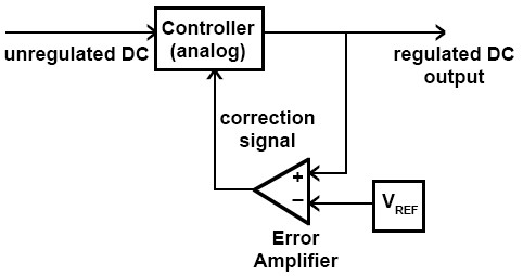
The analog supply: Supply regulation has traditionally been implemented using closed-loop negative feedback with analog circuitry in a switching regulator, Figure 1. (The alternative, a low-dropout regulator, or LDO, is also an option, but is viable primarily for loads under a few amps.) There are many standard, mature architectures for these switchers, with a long list of additional enhancements to increase efficiency across the entire load range, boost performance and ensure consistent operation. These enhancements can become quite complicated and clever and have impressive names such as SEPIC (single-ended primary-inductor converter). They use some form of pulse-width modulation (PWM), where the controller modulates the duty cycle to maintain the output at the desired DC voltage despite line/load changes. An output filter (not shown) smooths the pulse-chopped output to yield a nearly ripple-free output.
These switching-supply topologies can become fairly efficient and sophisticated, but all have one drawback: they lack flexibility for real-time setting of operational parameters. For example, the Intel/Xilinx VR13 standard requires the supply to implement adaptive voltage scaling (AVS), dynamically adjusting its output voltage from 1.2 to 0.9 V depending on processor clock speed and loading, while also compensating for process and temperature variations within the processor.
The hybrid analog/digital supply: An all-analog supply cannot do this. The solution is to use a hybrid-supply approach with an inner, fixed-function analog-control loop as before, which also allows digital supervision via setting of some loop parameters along with reporting of supply status, Figure 2. The core control algorithm is still established by hardware but some of its operating parameters can be changed, such as target output voltage, loop time constant, bandwidth and setpoints.

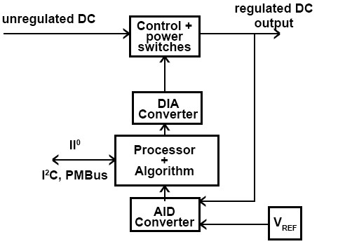
The fully digital supply: The all-digital supply uses a radically different internal architecture. Rather than implement the control loop using analog circuitry – even with some digital oversight – the digital supply relies on analog/digital (A/D) converters to digitize critical internal voltages and currents at tens of kilosamples/sec. The converted values are used by a dedicated, embedded processor (often an FPGA) that executes code for closed-loop algorithms. Finally, the algorithm’s “decisions” are converted back to analog signals via digital/analog (D/A) converters to adjust the PWM voltages and currents as needed, Figure 3. This is all done on a real-time, continuous basis.
Since the control algorithm is firmware-based rather than a hardwired analog circuit, the control strategy can be fairly complicated and sophisticated. Further, a more-powerful processor can manage two or more independent output rails, and coordinate these rails to control their output levels, ramp rates, and relative power on/off timing, all without the need for a separate power-management IC. It can invoke different control algorithms at different segments of the load curve, thus dynamically adjusting itself for optimum performance. Finally, it can provide detailed reports and historical data on the supply's status, conditions and changes, so likely failures can be anticipated rather than just reported after they occur.
Digital power is no longer restricted to output current in the double-digit range; it has migrated down to much-lower output levels. For example, the Renasas/Intersil ZL9006M DC/DC power module (Figure 4) operates over a wide input-voltage range and delivers between 0.6 V and 3.6 V at up to 6 A. It has built-in PID control-loop and auto-compensation algorithms, and a PMBus interface, all in a thermally enhanced, compact (17.2 mm × 11.45 mm), low-profile (2.5 mm) package which requires no external inductors.

Summary
The power needs of many of today's electronic systems can no longer be satisfied by even leading-edge analog supplies, but instead require a new form of power-supply architecture for control. The fully digital power-supply implementation has significant and tangible benefits with its flexibility, performance and adaptability. It is very different in concept and execution than the traditional analog-based supply – which remains the most viable solution at the lowest power levels for the foreseeable future – but the digital design is mature and is expanding to a broader range of applications and lower power ratings.
References
- iWatt White Paper, “What is Digital Power?”
- Sanken Semiconductors, “What is Digital Power Supply?”