Fusion 360 Used with KiCad to Produce Unique PCB Diffuser Clock
August 26, 2022
Blog
Printed circuit boards are, at their most basic, a way to arrange conductors that travel between solder-mounted parts. At the same time, they’re extremely strong sections of precision-cut and coated fiberglass, that could have structural uses as well.

(Image Credit: Jeremy Cook)
For my latest clock build, I designed a rather conventional PCB that mounts 85 SK6812 addressable LEDs and a Wemos S2 Mini board. A separate face PCB that has no circuitry at all, and features cutouts in the solder mask for each character segment, as well as a rectangular display area.

Cardboard prototypes before ordering the first PCB (Image Credit: Jeremy Cook)
Whether or not such a board counts as a printed circuit board is a bit of a philosophical discussion, but the results, as seen in the video below were quite good:
The larger goal of this PCB clock is to have several of them stacked side-by-side, allowing me to view multiple time zones at a glance. To this end, the PCBs have LED data input and output connections, which actually came in very handy as I was debugging the board, as they can be used to check the LED functionality.
Fusion 360 to DXF to KiCad
Electrically this design was fairly straightforward–control addressable LEDs with an ESP32 output, break out other pins for future use. The mechanical design was a bit more interesting, and since KiCad’s mechanical drafting capability is limited, I modeled the clock in Autodesk Fusion 360, exported the front and back PCB designs as DXFs, and imported them into KiCad.

(Image Credit: Jeremy Cook)
To prepare a DXF for export from Fusion 360, select Create Sketch, then click on the surface you’d like to reproduce to enter sketching mode. Click on the surface again to activate its features, then click Finish Sketch. Double check that the sketch has the features of the selected surface, which you can then export by right-clicking on the sketch under the sketches list, and selecting Save As DXF. Save this to your desktop or somewhere that you can easily find.

(Image Credit: Jeremy Cook)
Once in the KiCad PCB Editor, select File > Import > Graphics, where you’ll be presented with a dialog for file selection, layer, scale, and more. Once placed, you can modify the layer using the kicad-action-tools plugin, available via KiCad 6’s Plugin and Content Manager. If you want to move different parts of a DXF to different layers, uncheck Group items in the input dialog.
This export/import technique was invaluable for this particular design. Using Fusion 360 made it trivial to 3D-print the inner divider for it, and to modify things based on issues with my first attempt. My understanding is that the Autodesk Eagle EDA package is included with Fusion 360, and is able to keep the electrical/mechanical sides synced. I haven’t tried this because I’m getting pretty comfortable using KiCad. However, Eagle is something to be considered if you’re starting from scratch on your EDA journey, as this would be quite a convenient feature.
Potential Improvements

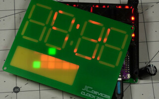
Green solder mask blocks red light well, but not green light. (Image Credit: Jeremy Cook)
One problem with this PCB clock face is that the solder mask on its own does not block all light, leading to some bleed-through. The solution on my next iteration will be to use a copper mask where light is not meant to penetrate, likely eliminating light transfer entirely. I could also coat the entire surface in solder mask, which would alleviate any visible marks on the substrate. However, in my initial testing with matte black mask, it appears to block too much light, and the light that does shine can reveal otherwise unnoticed visual marks.
There is still a lot to do on this project before it’s “done,” but I’m excited to one day be able to get data from multiple time zones (or other information sources) at a glance. I’m also pleased with what I’ve been able to learn while working on this project, including using hierarchical sheets to organize larger projects.
Jeremy Cook is a freelance tech journalist and engineering consultant with over 10 years of factory automation experience. An avid maker and experimenter, you can follow him on Twitter, or see his electromechanical exploits on the Jeremy Cook YouTube Channel!