An Almost Pure DDS Sine Wave Tone Generator: Part 2
March 20, 2020
Story
In part 2, we will cover how to implement a high precision NCO in software. Building a high precision ac tone generator with similar or better distortion performance than the best analog oscillators.
In part 1 of this series, we see how it is possible to design a very accurate sine wave generator based on the direct digital frequency synthesis (DDFS) principle, but implemented in software onto a floating-point DSP processor. In part 2, we will cover how to implement a high precision NCO in software.
Building a high precision ac tone generator with similar or better distortion performance than the best analog oscillators, as in the most famous Hewlett-Packard analyzers or as described in the application note AN-1323 is not a trivial thing, even if dedicated to the audio frequency spectrum (dc to 20 kHz range). Nevertheless, as written previously, a full software implementation, performing the phase calculations (ωt) and sine function (sin(ωt)) approximations using the adequate arithmetic precision of an embedded processor, can certainly help to minimize the quantization side effects, noise, and resulting spurs. This means that all the NCO functional blocks of Figure 2 are translated in lines of code (no VHDL!) to realize a software version that will meet real-time constraints to ensure the minimum sampling rate and the desired frequency bandwidth.
For the phase-to-sine amplitude conversion engine, the full LUT scheme or any variation demands too much memory or too many interpolation operations to achieve a perfect sine conformity. On the contrary, the polynomial method for sine approximation offers a very good complexity vs. accuracy trade-off by allowing the use of a very low cost, general-purpose DSP. Polynomial series expansion is also very attractive for its relative simplicity and ability to provide full flexibility in the choice of the type of power series, in tailoring the algorithm for a given precision. It does not require a large memory space, less than 100 lines of SHARC DSP assembly lines, and just a few RAM locations to store the polynomial coefficients and variables as sine values are only computed at sampling time instants.
At first, the obvious choice for a sine approximation function would be to use a straight Taylor/MacLaurin power series with the appropriate order to meet the targeted accuracy. However, since power series tend to lose effectiveness at endpoints, it is mandatory to reduce the argument input range to a smaller interval before performing any polynomial evaluation. Without argument range reduction, high precision over the function domain such as [–π, +π] can only be supported with very high order polynomials. Thus, some transformations need to be applied to the elementary function to get the reduced argument such as sin(|x|) = sin(f + k × π/2) and sin(f) = sin(x – k × π/2) with 0 ≤f<π/2. Consequently, extreme care should be taken with the trigonometric functions to avoid subtraction cancellations, which would lead to a serious loss of precision and produce catastrophic results, particularly with a poor arithmetic precision. In our case, this might occur when the phase input is large or close to an integer multiple of π/2.
Besides the periodicity and modulo-2π repetitions, the symmetric properties of the sin(x) function can be applied to further reduce the range of approximation. Given the fact that the sine function is antisymmetric about the point x = π for the interval [0, 2π], so it is possible to use the following relationship:
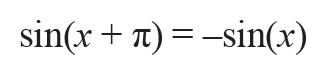
to reduce the range to [0, π]. In the same manner, sin(x) shows a symmetry about the line defined by x = π/2 for the interval [0, π], such that:
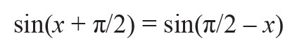
for x in the interval [0, π/2], which reduces the angle input approximation range even more. Further argument reductions to smaller intervals like [0, π/4] to improve the accuracy is not efficient because it requires both the evaluation of the sine and cosine functions at the same time as dictated by the common trigonometric relationship: sin(a+b) = sin(a) × cos(b) + cos(a) × sin(b), worthwhile for the generation of quadrature tones.
Analog Devices’ ADSP-21000 Family Application Handbook Volume 1 describes an almost ideal (for embedded systems) sine approximation function based on an optimized power series written for the first ADI DSP floating-point processor, namely the ADSP-21020, which is basically a SHARC core. This implementation of sin(x) relies on a minimax polynomial approximation that was published by Hart et al.4 and refined by Cody and Waite5 for floating-point arithmetic to mitigate round-off errors and to avoid the occurrence of cancellations as previously mentioned. The minimax method relies on Chebyshev polynomials and the Remez exchange algorithm to determine the coefficients for a desired maximum relative error. As shown with MATLAB in Figure 3, small changes in the set coefficients result in a dramatic increase in accuracy for minimax compared to Taylor for a seventh-order Taylor polynomial.6 For the best accuracy vs. speed trade-off, the angle input range of this sine approximation function is shrunk to the [–π/2 to +π/2] interval and the software routine includes an efficient range-reduction filter, which counts for about 30% of the total “sine” subroutine execution time.
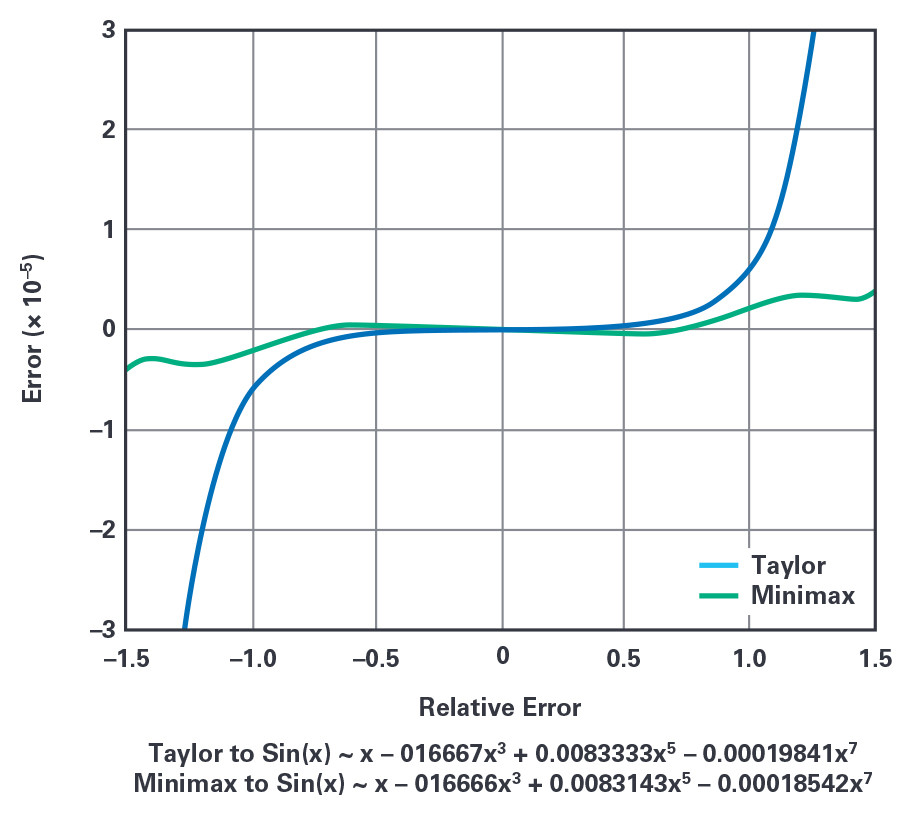
Figure 3. Unlike the Taylor-MacLaurin method defined around 0, the minimax sine approximation approach minimizes and equalizes the maximum relative error over the [–π/2 to +π/2] interval.
While all the computations could be executed with 32-bit fixed-point arithmetic, the most common and convenient format for mathematical calculations especially when dealing with long numbers has been for years the IEEE 754 floating-point standard. At the time, there was no single-chip floating-point DSP processor at all, but only simple floating-point multiplier and ALU computation ICs such as the ADSP-3212 and the ADSP-3222, respectively. This format replaced most of the proprietary formats of the computer industry and became the native format for all the SHARC DSP processors, in single precision 32-bits, extended precision 40-bits, and recently, double precision 64-bits for the ADSP-SC589 and ADSP-SC573.
The SHARC 40-bit extended single precision floating-point format with its 32-bit mantissa provides enough precision (u 2–32) for this sine wave generation application and to keep things equal, Cody and Waite show that a 15th order polynomial is appropriate for an overall accuracy of 32 bits with an evenly distributed error over the [0 to +π/2] input domain. The final tweak to minimize the number of operations and maintain accuracy is to implement the Horner’s rule for the polynomial calculation, a fast exponentiation method to evaluate a polynomial in one point, such that:
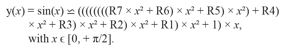
R1 to R7 are the Cody and Waite coefficients of the polynomial series and only eight multiplies and seven additions are necessary to evaluate the sine function for any input argument ε[0, π/2]. The complete sin(x) approximation code written in the form of an assembly subroutine is executed in about 22 core cycles on a SHARC processor. The original assembly subroutine was modified to perform simultaneous double memory accesses when fetching the 40-bit polynomial floating-point coefficients to save six cycles.
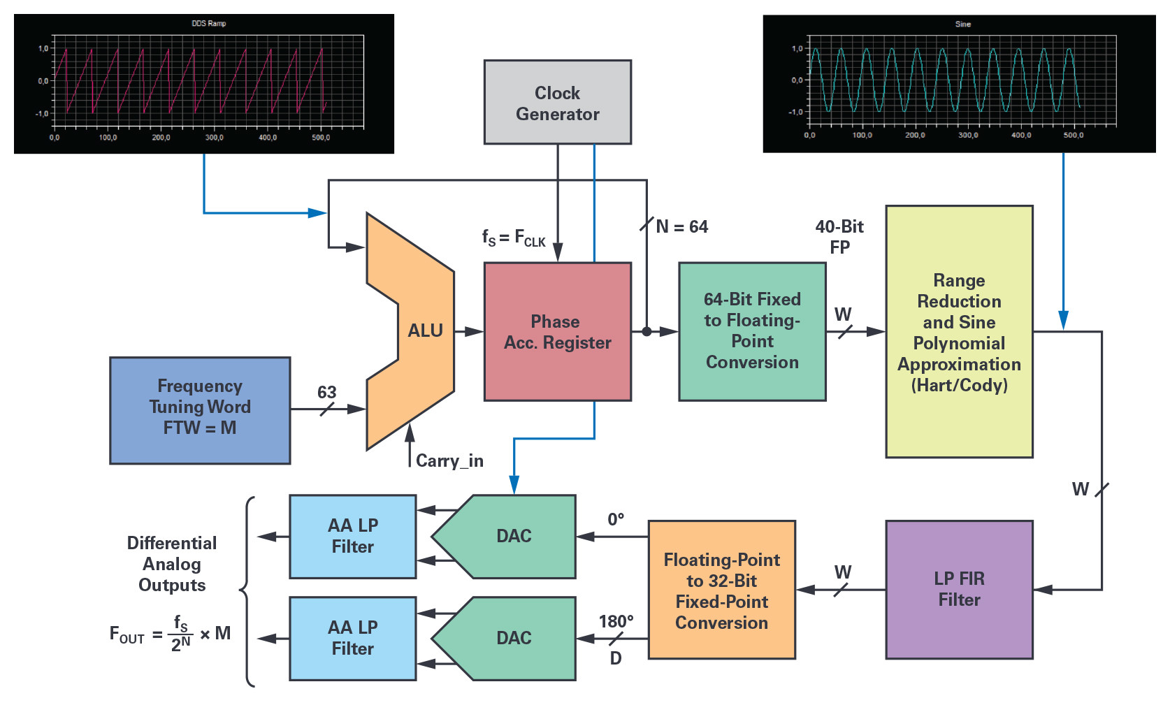
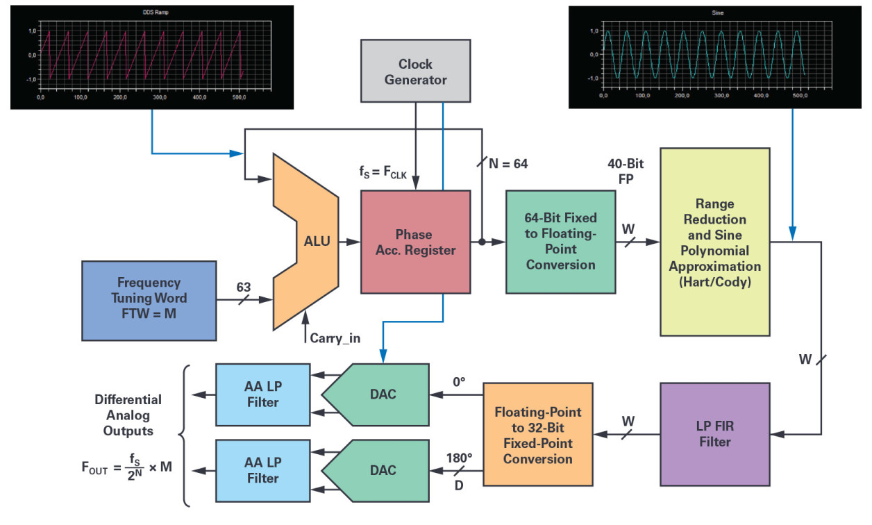
Figure 4. The software DDS simplified block diagram gives the data arithmetic formats and locations of the various quantization steps between the processing elements.
The NCO 64-bit phase accumulator itself is making use of the SHARC 32-bit ALU in double precision two’s complement fractional format for its execution. A complete phase accumulator execution with memory update costs 11 core cycles, and as a result, every NCO output sample is generated in about 33 core cycles.
The diagram in Figure 4 shows the functional block implementation of the software DSP-based NCO with some reference to the arithmetic format precision at each stage. In addition, one or two DACs and their analog antialiasing filter circuitry are required for the signal analog reconstruction, and to realize the complete DDFS. The key elements of the processing chain are:
- the 64-bit phase accumulator (SHARC ALU double precision addition with overflow);
- the 64-bit fractional fixed-point to 40-bit FP conversion block;
- the range reduction block [0 to + π/2] and quadrant selection (Cody and Waite);
- the sine approximation algorithm (Hart) for the phase-to-amplitude conversion;
- the sin(x) reconstruction and normalization stage over the –1.0 to +1.0 range;
- the LP FIR filter and sin(x)/x compensation if necessary;
- and the 40-bit FP to D-bit fixed-point conversion and scaling function to fit with the DAC digital input.
An optional, digital low-pass filter can be placed at the output of the NCO to remove any spur and noise that could fold in the band of interest. Optionally, this filter can provide interpolation and/or inverse sin(x)/x frequency response compensation depending upon the DAC selected for the analog reconstruction. Such a low-pass FIR filter could be designed with the MATLAB Filter Designer tool. As an example, assuming a 48 kSPS sampling frequency and a dc to 20 kHz bandwidth with a 0.0001 dB in-band ripple and a –150 dB out of band attenuation, a high quality equiripple filter could be implemented with 40-bit floating-point coefficients. With only 99 filter coefficients, its total execution time will consume about 120 SHARC core cycles in single instruction, single data (SISD) single-computation unit mode. After digital filtering, the pairs of calculated samples are sent by DMA to the DACs using one of the DSP synchronous serial ports. For a better speed performance, chaining DMA operation is also possible with large ping-pong memory buffers to support processing by block operation. For example, the block data size could be equal to the length of the FIR data delay line.
Final Tweaks at the NCO for an Optimal SFDR
As mentioned earlier, the NCO suffers from spurs mainly due to the truncation of the phase accumulator output and, to a lesser extent, from the amplitude quantization done on the sinusoidal values obtained by calculation or by tabulation. The error due to phase truncation generates spurs around the carrier frequency by phase modulation (sawtooth), while sine amplitude quantization causes harmonically related spurs although were considered as random errors and noise for a long time. Today, the operation of the phase accumulator is mathematically perfectly known as described in a technical paper7 from Henry T. Nicholas and H. Samueli. After a thorough analysis, a model is presented such that the phase accumulator is considered a discrete phase sample permutation generator from which the frequency spurs can be predicted. Whatever the phase accumulator parameters (M, N, W), the length of the phase sequences equal to
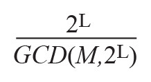
(where GCD is the greatest common divisor) is determined by the rightmost bit position, L, of the frequency tuning word, M, as shown in Figure 4. Hence, the value of L defines sequence classes, each sharing their own set of phase components, but permutated according to the
ratio. These sequences of truncated phase samples generated in the time domain are used to determine, by DFT, the respective location and magnitude of each spurious line in the frequency domain. These sequences also demonstrate that odd values of M (FTW) exhibit the lowest frequency spur’s amplitudes and suggests a simple modification of the phase accumulator to satisfy these minimum conditions by simply adding 1 LSB to the FTW. This way, the phase accumulator output sequences are forced to always have the same 2N phase elements, whatever the M value and the initial content of the phase accumulator. The level of the worst spurious tone magnitude is then reduced by 3.922 dB and equal to SFDR_min (dBc) = 6.02 × W. The Nicholas modified phase accumulator confers several benefits to the NCO, as first it eliminates the cases where the rightmost bit of the FTW is too close to its MSB (frequency sweep in FMCW applications), and, secondly, it makes the spur’s amplitude independent of the frequency tuning word, M. This modification is easily implemented in software by toggling the ALU LSB at the sampling rate fS, the same behavior of the phase accumulator could be simulated as if the FTW LSB was set to logic 1. With a phase accumulator size N = 64 bits, a ½ LSB offset can be considered as a negligible error regarding the accuracy of the desired frequency FOUT.
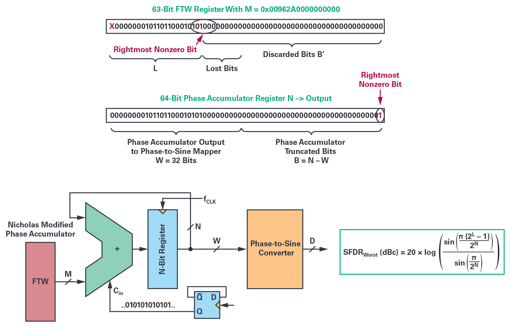
Figure 5. The position of the rightmost, nonzero bit of the FTW sets the theoretical SFDR worst-case level. The Nicholas modified phase accumulator solves the issue for any value of N and maximizes the SFDR of the NCO.
With an output phase word, W, of 32 bits, the maximum spur’s amplitude due to phase truncation is therefore limited to a value of –192 dBc! Finite quantization of the sine sample values also leads to another set of frequency spurs, and it is commonly considered as noise and estimated by the well-known relationship SNRq(dB) = 6.02 × D + 1.76. This must be added to the parasitic elements due to the approximation errors of the phase-to-sine amplitude-conversion algorithm stage which, however, are considered negligible, given the extreme care in the choice of the phase-to-sine approximation algorithm and the calculation’s precision.
These results indicate that both the linearity and the noise of our software sinusoidal NCO are at theoretical levels well beyond the required thresholds to test most of the high precision ADCs available on the market. It remains to find the last, but most critical elements of the signal chain: the reconstruction DAC and its complementary analog antialiasing filter and associated driver circuitry susceptible to meet the expected level of performance.
In part 3 of this series, we will cover how to select the reconstruction DAC and complete the DDFS system.
About the Author
Patrick Butler is a field applications engineer with Analog Devices’ south Europe sales organization, supporting the French global market and some ADEF customers. He has been with ADI since 1984, supporting the DSP building blocks ICs, as well as high speed converters. Previously, he worked as a design engineer in the ATE division of Schlumberger in Saint-Étienne, France for five years, and then occupied several application engineer and FAE positions at Matra-MHS in Nantes, AMD and Harris SC-Intersil. Today, his main hobby is collecting vintage sound components to build active, high efficiency horn loudspeaker-based systems with the help of his two sons.
3 Jim Williams and Guy Hoover. AN-132: Fidelity Testing for A→D Converters Proving Purity. Analog Devices, Inc., February 2011.
4 John F. Hart. Computer Approximations. Krieger Publishing Company, 1978.
5 William J. Cody and William Waite. Software Manual for the Elementary Functions. Prentice-Hall, Inc., 1980.
6 Robin Green. “Faster Math Functions, Part 2 Presentation.” Sony Computer Entertainment America, May 2016.
7 Henry T. Nicholas and Henry Samueli. “An Analysis of the Output Spectrum of Direct Digital Frequency Synthesizers in the Presence of Phase-Accumulator Truncation.” IEEE, May 1987.