Budget Tools Review: Exploring I2C With the Digilent Analog Discovery 3
August 07, 2023
Blog
In my most recent Budget Tools Review I discussed the extremely versatile Digilent Analog Discovery 3 (DA3). One might call it a computer-based oscilloscope, but it’s much more than that. Today I’ll be using it, along with its companion software package Waveforms, as a Logic Analyzer and Protocol Analyzer to dive into I2C.
The I2C protocol uses a clock line (SCL) as well as a data line (SDA) to communicate between a master device with one or more slave devices, using a 7-bit addressing system.* It also needs power and ground lines, and resistors on SDA and SCL to pull each line high when not in use. I did not add external resistors for this experiment. Presumably, they are built into the tested slave device.
Connect your hardware, set things up in software with the correct address, and you’re in business. That’s a bit of a simplification, but it does tend to work quite well. I wanted to see how the protocol worked on a very low level, and the Analog Discovery 3 is a perfect tool for this job.
Hardware Setup
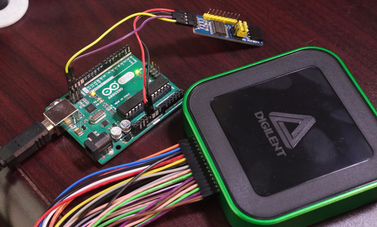
For my setup, I used an Arduino Uno board to generate I2C signals, along with a readily available PCF8574 I2C GPIO expansion breakout as a slave device. This expansion board includes input and output sets of pins for SDA, SCL, power, and GND. I added an LED–with series resistor as I felt like behaving myself–for visual feedback. Signals can be input to one set of contacts and monitored via the DA3 on the other set.
To set the DA3 and Waveforms up to record I2C signals, open the logic analyzer in the welcome dialog, then click the plus to add channels. Select I2C and assign the appropriate pins for clock and data. Click Protocol, select I2C, then click OK. Hit Single or Run to record I2C signals.
Logic Analyzer Analysis
.png)
Image Credit: Screencap, Jeremy Cook
I sent on/off signals to a GPIO expander at address h3c via code found in this repository. While it’s easy enough to research I2C, interacting with it live takes things to another level. This is one reason why the DA3 could be such an excellent educational tool. Looking at the results, the protocol goes through the following:
- Start condition – master pulls data line SDA low directly before pulling SCL low as well to initialize transmission
- Clock pulses high every 20µS, allowing 7 bits for addressing, and an 8th bit to indicate read or write, registered on the falling edge from the data line. For example, 01111000 means 0111100 for the address, or 3C in hex. The 0 at the end indicates the master will write to the slave
- The slave acknowledges the address frame by pulling the data line low
- Once the ack bit is received, an 8-bit data frame is sent
- Acknowledge procedure repeated, additional data frame/acknowledge procedures may be sent as required
- Stop condition – Master releases SCL high then releases SDA high, the opposite of the start condition
This is a bit of a simplification, and you can get a more rigorous explanation of how I2C works in other places–e.g. this article on Analog.com. However, being able to interact with waveforms live in real-time gives you a familiarity with the protocol that would be difficult to obtain otherwise.
Protocol Analyzer (The Easy Way)
.png)
Image Credit: Screencap, Jeremy Cook
If you just want to see what the protocol is saying, without delving into the low-level details, the DA3 makes this quite easy. Click Protocol in the welcome dialog and select I2C as the protocol, then the appropriate DIO pins for SCL and SDA. Attach the SDA, SCL, and ground pins. Hit receive, and you’ll be presented with the bus signals in hex.
The format here is illustrative of the protocol, e.g. the line below sets P0 to high:
Start, h78 [ h3C | WR ], h03, Stop
Here the start condition is sent, then h78 (01111000), broken down in brackets into h3c (011100) plus the write bit (0). This is followed by h03 as the data frame, then the stop condition.
Address Test Analysis
The PCF8574 breakout has several jumpers for selecting its address, but rather than shaving that yak, I instead used I2C scanner code in the repository linked above. With the code loaded, the I2C address is shown on the Arduino IDE serial monitor, though there’s a lot more going on behind the scenes. Shown below, PCF8574 inputs were connected, and outputs analyzed by the DA3:
.png)
Image Credit: Screencap, Jeremy Cook
You can zoom in and out with the middle mouse button and pan around with the slider toward the top of the window in the logic analyzer. This can be very helpful for getting a better picture of what’s going on and for setting an appropriate sample rate. Note that the logic analyzer and protocol analyzer cannot be used simultaneously, but you can alternate between the two as needed.
DA3: I2C and Much, Much More

Image Credit: Jeremy Cook
While this post has explored the I2C protocol with the DA3, this ability is but the tip of the iceberg for this piece of computer test equipment. As noted in my review, it has a total of 14 different tools, and can act as an alternative and/or supplement to traditional test equipment. While $379 isn’t pocket change, you get a massive amount of value in a pocket-sized package.
*Master/slave devices may be referred to as controller/node or controller/peripheral depending on the publication. In some instances, a bus may have multiple masters, and /or a 10-bit addressing system can also be implemented.