Protecting Intelligent Outlets in Smart Homes
June 04, 2020
Story

Innovation in wireless and internet technology is converting common, non-intelligent devices into smart devices that help users leverage the Internet of Things (IoT).
Innovation in wireless and internet technology is converting common, non-intelligent devices into smart devices that help users leverage the Internet of Things (IoT). This trend is occurring in our homes, workplaces, and buildings. IoT technology has entered the home creating the smart home with products for convenience, security, lighting control, entertainment, and environmental control.
To enable these advances, traditionally non-intelligent devices such as light dimmers and power outlets must be intelligent and are becoming widely adopted in the latest home and building designs. The smart power outlet market is growing at a compound annual growth rate of around 25%1, and the market is estimated to reach 45M units/year in 2024. The smart light dimmer market is forecasted to be growing at over 15%2 and is estimated to reach 15M units/year by 2024.
Other devices such as ground-fault circuit interrupters (GFCIs)/arc-fault circuit interrupters (AFCIs) and USB outlets are becoming more intelligent. The market for GFCI/AFCI devices is roughly estimated to have a growth rate of around 5%, while the USB market is estimated to be growing at a rate of 10%. Protecting all these devices with overvoltage and overcurrent protection is essential for long term reliability and safety.
What makes a device intelligent?
An intelligent device has electronic circuitry that enables control, system coordination, and status feedback. The intelligent device can be programmed by audio (voice), manual, or electronic control. An IoT intelligent device can be accessed and programmed remotely through a wireless communication protocol such as cellular, WIFI, or Bluetooth. Your personal computer, tablet, smartphone, or virtual assistant can easily communicate with these intelligent devices.
Designing for safety and reliability
Designers need to ensure that these new smart devices are safe and reliable as consumers expect high reliability without risk of service interruption. Thus, the devices require overvoltage protection and overcurrent protection to maintain operation even when subjected to a wide range of environmental hazards such as lightning surge, induced power surge, electrostatic discharge, and electrical fast transients. This article informs designers about the types of components to use and where in the circuit architecture they should be applied.
Design considerations for smart devices connected to the power lines
Intelligent outlets are connected to incoming AC power lines and will need to meet agency standards and reliability expectations. Typically, a fuse is used for overcurrent protection. The fuse will interrupt if a current exceeding its rating occurs over a defined period. When selecting a fuse, consider normal operating current, application voltage, ambient temperature, overload current conditions, maximum fault current, resistance, and agency approval.
A lightning strike can create an induced power surge on the power line creating an overvoltage transient which can cause failure. For protection, the designer typically selects metal oxide varistors (MOVs) and/or transient voltage suppression diodes (TVS). MOVs and TVS are both designed to absorb transient current surges. TVS diodes have a faster response time of under a picosecond, and MOVs can absorb more energy depending on the specific component selected. The right component choice depends on exact system layout and other components in the system. Operating voltage, clamping voltage, surge requirements, and component costs need to be considered.
Primary fuse parameters:
- Current rating
- Maximum operating voltage
- Interrupting current rating
- Series resistance
Primary MOV parameters:
- Maximum transient energy absorbed
- Maximum peak surge current
- Maximum continuous operating voltage
- Clamp voltage
- Operating temperature range
Primary TVS Diode parameters:
- Reverse standoff voltage
- Peak pulse power dissipation
- Breakdown voltage
Protecting the wireless communication microprocessor from Electrostatic Discharge (ESD)
The wireless communication circuitry for intelligent outlets is exposed to the external environment including human touch and should have protection, primarily, from ESD. Choosing the best suppression technology depends on threat level, system architecture, and form factor.
ESD suppression components protect both wireless chipsets and the digital circuitry behind the wireless interface. TVS diode arrays and polymer ESD suppressors are two solutions. TVS diode arrays have the advantages of lowest possible clamping voltage and minimum package size. Both components have low leakage current and low capacitance of under 1 pF. A typical TVS diode used for this application will withstand +/- 12 kV ESD in accordance with the IEC 61000-4-2 standard.
Both TVS diode arrays and polymer ESD suppressors have small footprints and consume a small amount of valuable pc board space. Of most importance, these devices, depending on the component selected, can withstand up to 30 kV from direct contact and up to 30 kV transmission through the air in compliance with IEC61000-4-2. The polymer ESD devices respond to ESD voltages in under a nanosecond while the TVS diodes respond in under a picosecond. If size is a major concern, the polymer ESD devices have a maximum footprint (length of pads) of 3 mm while the TVS diodes can have a maximum footprint of 9 mm.
Primary polymer ESD parameters
- Standoff Voltage
- Clamp voltage
- Trigger voltage
- Capacitance
- Leakage current
Protection and control for smart light dimmers and smart power outlets
Both smart light dimmers and smart power outlets obtain power from the power line; thus, they require power line protection. Both devices have wireless communication interfaces as well which require protection from ESD. ESD protection is also needed to protect circuitry from a manually-controlled switch and other contact points during production and installation. The typical options for overcurrent protection, overvoltage protection, and power control are shown in Figure 1.
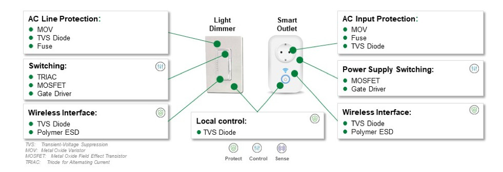
Figure 1. Recommended protection and control components for smart light dimmers and smart power outlets.
Figures 2 shows a block diagram for the smart light dimmer and Figure 3 shows the block diagram for a smart outlet. The recommended protection and control component options are shown in the list adjacent to the block diagrams
Power control for smart light dimmer and power outlets
Smart outlets employ Schottky rectifiers for rectification in the switching power supply which powers the DC circuitry. Schottky rectifiers have a low forward voltage. The low forward voltage improves power conversion efficiency. Furthermore, Schottky diodes have fast switching speeds that enable switching power supplies to operate at high frequencies for additional improved efficiency.
In dimmers, the TRIAC is used to control the percentage of the AC waveform that is output to the light. For low, load current, light sources such as LEDs, TRIACs can have a holding current as low as 6 mA. Another option to control the light source is a MOSFET. MOSFETS have fast switching times and low on-resistance to minimize power loss and improve efficiency of the power transfer from input to output. A gate driver controls the MOSFET and ensures efficient turn-on and turn-off of the MOSFET.
Primary Schottky diode parameters
- Forward voltage
- Forward current
- Reverse voltage
- Reverse Recovery Time
Primary TRIAC parameters
- On-state current
- Voltage rating
- Holding current
- On-state current rate of rise
Primary MOSFET parameters
- Drain-Source current
- On resistance
- Switching time
Primary MOSFET gate driver parameters
- Input voltage
- Output current

Figure 2. Block diagram of a smart light dimmer. The safety and control component options recommended for the circuit blocks are shown in the list adjacent to the block diagram.
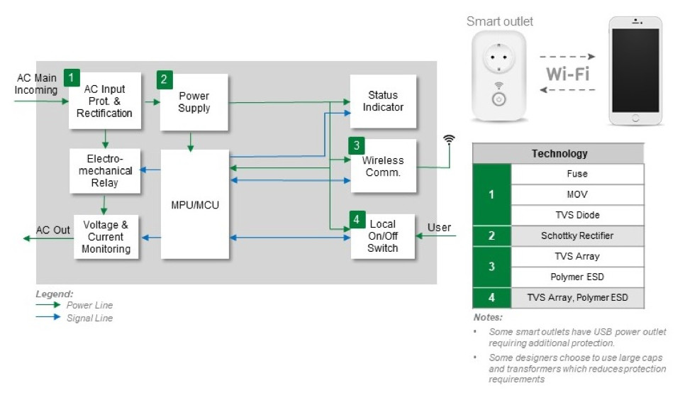
Figure 3. Smart outlet block diagram showing where protection and control components are required. The table lists the recommended component options.
Ensure protection and control for GFCIs, AFCIs, and USB outlets
The original intelligent devices for the home are the GFCI and AFCI. The GFCI senses when the load current delivered on the hot line does not return on the neutral line. If the current imbalance exceeds a pre-determined trip level, the GFCI removes power from the outlet to prevent an electric shock hazard. The AFCI detects an arc condition and removes power from the outlet to prevent a fire.
Power outlets with USB charging have become more common in residential and public locations. These outlets may have USB charging combined with historical power outlets or multiple USB chargers in a single device. GFCI, AFCI and USB chargers need protection from transients. Figure 4 shows the recommended protection and control components needed for GFCIs, AFCIs, and USB charging outlets.
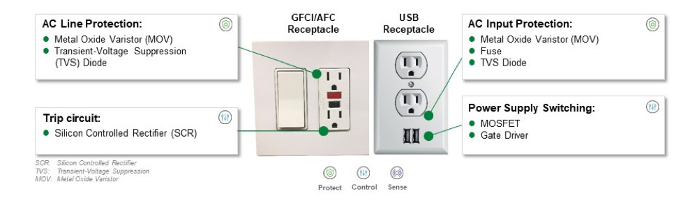
Figure 4. Recommended protection and control components for GFCIs, AFCIs, and USB charging outlets.
The block diagram for the GFCI and AFCI are shown in Figure 5. The protection components are similar for smart light dimmers and smart outlets. The recommended power control component is an SCR. The SCR activates the relay that disconnects the AC main incoming power to the output when a current imbalance is detected. Also, SCRs are available in a variety of through-hole and surface mount packages. They also will come with isolation voltages as high as 2500 Vrms.
Primary SCR parameters
- On-state current
- Blocking voltage
- Forward drop
- Gate current trigger level
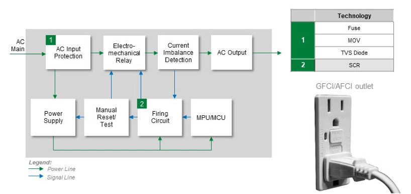
Figure 5. Block diagram of a GFCI or an AFCI. The adjacent table lists the recommended protection and control component options.

Figure 6. Block diagram of a USB outlet. The recommended protection and control component options are shown in the adjacent list.
Save development time with knowledge of the applicable industry safety standards
Meeting UL standards or IEC standards is required for these intelligent devices since all of them operate on line power. The specific standard that is applicable depends on the global location where the device will be used. Missing a standard requirement can result in extended product development time and added project costs if a certifying body fails to approve your product. Table 1 contains a list of the applicable national and international standards for these types of products.
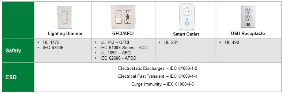
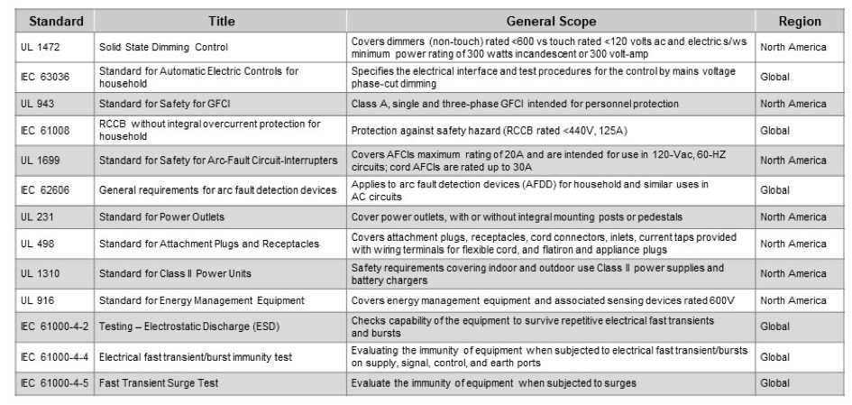
Table 1. List of Applicable National and International Standards and Compliances
For more information on Littelfuse circuit protection solutions, refer to the following documents:
- Fuseology Selection Guide
- Circuit Protection Products Selection Guide
- Electrostatic Discharge (ESD) Suppression Design Guide
Or contact Littelfuse at www.littelfuse.com for design assistance from application specialists.
1Global Smart Outlet Report 2019. Industry Research. March 2019.
2Report on Global Dimmers Market. Market Research Future. Jan 2020.
About the Author
Craig Morrow is a Global Strategic Marketing Manager for the Electronics Business Unit at Littelfuse. He joined the Electronic Business Unit from the Semiconductor Business Unit where he held a role in business development and sales. Craig came to Littelfuse via the acquisition of IXYS in January of 2018. Craig received an MBA from UCLA, a MSEE from Auburn University, and a BSEE from Tennessee Technological University. Craig can be reached at [email protected]