Maximize Mobile Point of Sale (POS) Uptime with Robust Protection Technologies
November 10, 2020
Story

Advanced design considerations can help avoid/completely eliminate damage caused by over-current, over-voltage, over-temperature conditions, increasing the reliability and lifetime of mobile devices.
Advances in mobile electronic technologies are enabling the creation of new and more capable portable point of sale (POS) devices. Users depend on the performance of these new devices to enable retail transactions from anywhere. Maximizing uptime and assuring high reliability are mission critical in any retail operation, from small stores to big box stores.
Challenges for designers include protecting their product from hazards such as electrostatic discharge (ESD) from human touch and overcurrent, and transient events from the AC power line when a power adapter is in use. Another challenge for designers is the need to develop products that extend battery life and safely accelerate battery re-charging time so that a POS terminal spends the least amount of time out of service. Use of lithium ion batteries enables the designer to provide high energy density in a small battery pack and can allow fast charging capability; however, the designer needs to manage the charge cycle and monitor the battery to avoid damage to the battery pack.
A third challenge for designers is ensuring their product complies with the applicable standards. Failure to adhere to a standard can prevent a new product from having a timely introduction to the market. Rejection of a product by a nationally recognized testing lab results in lost revenue due to re-design work and re-testing resulting in delays in delivering the product to the market.
Designers have many components that they can choose for product protection and problem detection including fuses, varistors, transient voltage suppressors, ESD suppressors, and temperature detectors. This article will provide designers guidance on where protection and sensing components are needed for POS terminals, their power adapters, and their printer modules. Figure 1 shows an older POS terminal, a newer terminal, and a power adapter along with a listing of the protection and sensing components that will enable robust products. Figure 2 illustrates the main elements of a POS terminal system.
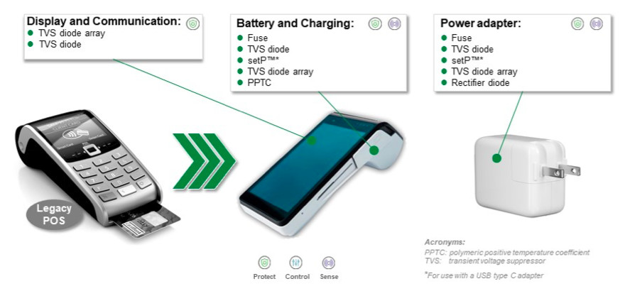
Figure 1. Mobile POS devices and recommended protection and sensing components
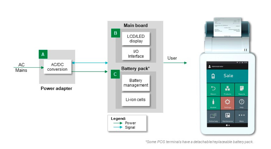
Figure 2: Mobile POS Terminal System Architecture
Protecting the Power Adapter
A power adapter connects to the AC power line; therefore, the power adapter will require AC line protection from overcurrent conditions, power line transients, and lightning strikes. Figure 3 shows the circuit blocks for a power adapter and the recommended protection components.
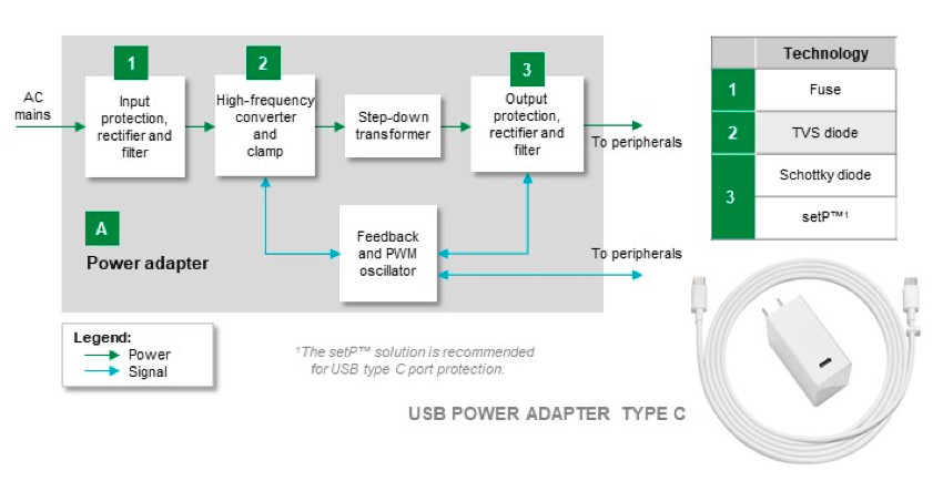
Figure 3. Power adapter block diagram with component recommendations
The protection components for the input protection, rectifier, and filter block include a fuse for overcurrent protection and a varistor for transient energy protection. Designers should consider whether their design requires a fast-acting or a slow-responding fuse. They need to ensure that the fuse has a voltage rating higher than the AC line voltage and that the resistance of the fuse is sufficiently low to minimize power consumption in the fuse. Based on the available PC board space, designers can select between cartridge fuses, axial-lead fuses, and surface mount fuses.
The high-frequency converter and clamp block also require protection from transients that propagate through the input block. For this block, designers can use transient voltage suppressor (TVS) diodes which are designed to protect sensitive electronic circuitry. These devices can respond within a picosecond to a transient. Designers have the option to select either bipolar or unipolar diodes; and, designers can use these components in either radial lead or surface mount form factors.
The output protection, rectifier, and filter block interfaces with external peripheral devices. A Schottky diode will provide reverse polarity protection from an incorrectly connected peripheral device. The low forward voltage of the Schottky diode will minimize power consumption in the device to allow maximum efficiency of the power adapter. Designers need to ensure that the Schottky diode can support the power adapter’s maximum output current.
If the output can charge USB Type-C devices, then it can be capable of outputting 100 W. While USB Type-C devices can charge with high power, 100 W, the USB connector has densely spaced pins which could easily be shorted by dust and dirt. Designers can protect the USB circuit from damage by monitoring the temperature rise in the USB connector. A digital temperature indicator can increase its resistance by five decades from 10 Ω to 1 MΩ when the temperature of the connector reaches around 100 °C. The rise in resistance will result in de-energizing the output from the power adapter. A temperature indicator designed specifically for use in a USB connector and compliant with USB Type-C standards will protect the USB connector and the output block from damage.
Protecting the Mobile POS Terminal
The POS terminal is subject to continuous contact from retail clerks and customers. Many retail establishments have carpeted floors which, combined with low humidity, facilitate an environment susceptible to ESD. Figure 4 shows the circuit blocks in a POS terminal.

Figure 4. POS terminal block diagram with component recommendations
The DC input block requires overcurrent protection and transient protection. Designers should consider saving PC board real estate with 0402-packaged surface mount fuses. Using a fast-acting fuse can protect the DC input block and the rest of the POS terminal by opening in response to a 200% overcurrent in a fast, 5 s. A TVS diode can provide protection against transients for the DC input circuit. Surface mount versions are available in either bipolar or unipolar versions. Surface mount versions can safely absorb up to 1500 W from a 10/1000 µs pulse.
The USB Type C input block needs the temperature protection that the output block of the power adapter required. In addition, the USB Type-C input block interfaces with the external environment; thus, protecting this block from electrostatic discharge (ESD) is a necessity. Designers can use a TVS diode array with up to five, bipolar diodes to protect all portions of this circuit block. The diodes can absorb a transient as large as ± 20 kV. Each diode has a capacitance of only around 0.2 pF so that the component has a negligible effect on the USB transmission protocol.
The blocks interfacing with the microprocessor, MPU, block should have transient protection so that both those blocks and the MPU remain safe. The storage and touchscreen display blocks can use a TVS diode and a TVS diode array respectively. The touchscreen, which users will contact, is especially susceptible to ESD. A multi-diode component can provide complete protection for the touchscreen circuitry.
The Wi-Fi block also is exposed to the external environment. A polymer composite ESD suppressor is the recommended component for ESD protection. Since an RF circuit is designed to maintain a 50 Ω characteristic output impedance, designers need to use a protection component that has an insignificant impact on the output characteristics of the circuit. A polymer ESD suppressor protects against ± 8 kV ESD transients from direct contact and ± 15 kV ESD transients from air discharge; and the component has a maximum capacitance of only 0.12 pF. The ESD suppressor has a leakage current of a few nanoamps. Thus, an ESD suppressor can provide the necessary protection without interfering with the GHz Wi-Fi RF signals.
While lithium ion battery packs have high energy density in compact cells, they can be susceptible to thermal runaway if subjected to an external short circuit. The battery management circuit provides protection features for the battery pack; however, designers should incorporate overcurrent protection for a battery pack. Designers should consider use of a resettable overcurrent protection component such as a polymer positive temperature coefficient (PPTC) component. This component has a maximum resistance of 150 mΩ; and for holding currents above 2 A, the resistance falls to milliohm levels. Trip time to an overcurrent is typically a maximum of 5 s; and, a PPTC is available in a space-saving, 0402 surface mount package. A PPTC component provides fast overcurrent response with a low power-consuming, series resistance to protect a lithium ion battery pack.
Protecting the Printer
The receipt printer for the POS terminal may be either integral to the terminal or a separate device. In either event, the printer requires protection from overcurrents, transients, and ESD. Figure 5 shows an example printer and recommended protection components. Figure 6 details the printer circuit blocks and the components required to protect specific blocks.
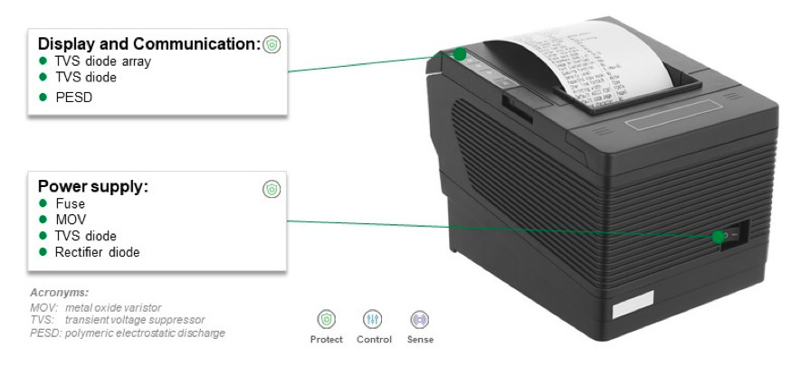
Figure 5. POS printer and recommended protection components
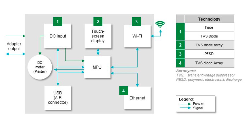
Figure 6. POS printer block diagram with component recommendations
The printer has three circuit blocks, the DC input, the touchscreen display, and the Wi-Fi block, that are similar to POS terminal circuit blocks and require similar protection components. The ethernet block interfaces with external circuitry and requires ESD protection. For this high data-rate, communication block, designers must select a protection component that does not compromise the transmission rate. Designers can consider a multi-pin TVS diode array that offers ± 20 kV of contact protection and ± 30 kV air discharge protection while loading the ethernet circuit with only 2 pF per I/O line. Figure 7 shows a recommended protection scheme using a Littelfuse 4-channel low capacitance, TVS diode array. The component also includes a Zener diode to enable absorption of 150 W and 10 A of an 8/20 µs transient pulse.

Figure 7. Recommended protection circuit for an ethernet interface using a low capacitance TVS diode array that includes a Zener diode
The printer’s USB connector block also interfaces with external devices; thus, it needs ESD and transient voltage protection as well. As with the Wi-Fi block, an ESD suppressor can protect I/O lines while adding minimum capacitance to the circuit. Versions of the device can protect a single port or two ports as shown in Figure 8.
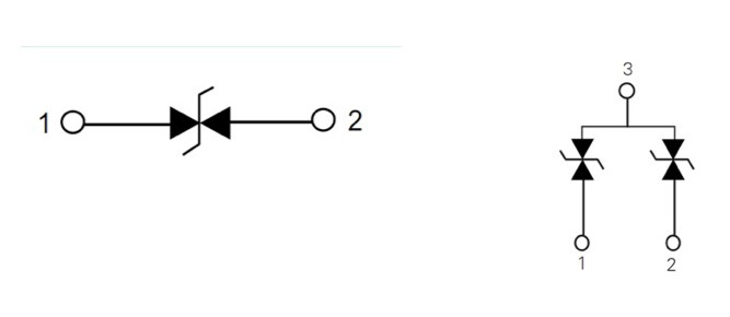
Figure 8. Single and dual port polymer ESD suppressors
Ensure compliance with national and international standards
Designers should be aware of the standards that apply to the elements of the POS terminal, its printer, and its power adapter. Table 1 lists some important standards with which products must comply so that they can be introduced to the market. These standards include requirements for USB interoperability, USB Type-C requirements, and safety requirements for information technology equipment. Other important standards include requirements for surviving levels of ESD protection and other transients. Standards exist for protection against lithium battery faults. A separate standard applies to power supplies and chargers that connect to the AC power line.
Not adhering to these standards can lead to rejection of a POS terminal by a testing lab. Designers will then be faced with costly re-design work, an expensive repeat of tests by the testing lab, and a loss in revenue due to delayed introduction to the market. Efforts to comply with the appropriate standards early in the design cycle will save substantial development time and costs. The product will then be higher quality and a more robust product.

Table 1. Standards applicable to POS terminals
Use all available resources to overcome the challenges
Designers need to employ circuit protection and sensing to develop reliable products. By doing so, the products will avoid field failures that create customer dissatisfaction and market perception of poor quality. Both impact product revenue. In addition, design teams need to be cognizant of the applicable industry standards so their products can obtain national testing lab certification and approval in the least amount of time. Using recognized components, such as Underwriters Laboratory recognized components, will substantially reduce testing lab certification time. Taking advantage of available resources, such as application engineers at manufacturers who specialize in the development and applications for protection and sensing components, can help overcome the challenges of designing a robust product that that is compliant with industry safety standards.
To learn more, download the Circuit Protection Selection Guide. For more information, visit www.littelfuse.com.