Virtual Prototyping Platform for Architecture Exploration and Functional Safety Analysis
May 26, 2021
Story

The pandemic sweeping the world, COVID-19, has rendered a large proportion of the workforce unable to commute to work, as to mitigate the spread of the virus.
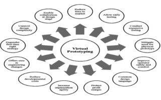
Due to the pandemic, most if not all workers experienced work from home (WFH) leading to temporary stop of traditional development and global collaboration methodologies. The alternative way for collaboration of software and hardware teams is required. Developing remotely can be a challenge in the age of social distancing since accessing remote and scare hardware, and systems for developing and testing is difficult. One feasible solution could be virtual prototyping that enables replacing hardware with software equivalent models of the hardware; at any time, and from anywhere.

The integration of increasingly complex hardware and software is a significant challenge for semiconductor and OEM companies developing next-generation wireless, consumer, and automotive devices. Traditional methods of serialized hardware and software development - where the vast majority of software is developed and verified after the silicon design is complete–often fail to meet aggressive product development schedules. Virtual prototypes are fast, fully functional software models of complete systems that execute unmodified production code and provide unparalleled debug efficiency.
Solutions for the automotive companies should have the ability to combine design and do integration test into a single virtual prototyping platform. Users can determine if the design and integration process will succeed instead of an open-loop design process that often results in design issues identified at integration test. The chosen platform here is VisualSim Architect (VSA) that can accomplish this with a closed-loop design/integration flow by being able to model a complete end-to-end design. The end-to-end design uses many pre-built, pre-tested automotive libraries that generate pre-defined reports to speed development, plus integration testing. The user can evaluate latency, throughput, sub-system utilization, and power of key sub-systems.
Other automotive solutions are focused on algorithm testing, software development, and software testing. The solutions are available as an Instruction Set Simulator to execute the software code without a board, SysML to document the software sequence, C-code generation, math correctness models, and testing solutions by loading software on prototype boards.
The above solutions are used much later in the design process. Hardware and software failures occur because of incorrect specification and not from incorrect manufacturing. These alternate solutions are validating the correctness against imperfect specification. Functional safety tests are done very late in the design cycle and manufacturing changes impact product quality. Current techniques do not allow for multiple failures across truly distributed systems. Making large-scale changes to the architecture at the integration or software development stage is time-consuming, expensive, and will delay the schedule.
VisualSim served the following criteria’s:
- Optimize the specification to meet timing, power, and functionality.
- Create a common executable specification for OEM and suppliers.
- ISO-26262 Parts 4, 5, and 6 are introduced for both design and verification.
- Integrate existing tools and simulators including MatLab and C-code for a time-driven analysis.
The failure types supported include:
- Power Failure: sudden power spikes, reduction in battery life
- Hardware Failures: Complete shutdown of a circuit board or core failure
- Redundant Impact: Handle increased load in the event of a failure
- Software Failure: Modified memory value, Resource Starvation
- RTOS Failure: Overrun on prior task causes the current task to fail
- Network Failure: corrupted messages or congestion within a network
- Cyber-security: Simulate attacks and evaluate algorithm quality on the system throughput
Analyzing a Model for Hardware Failure
According to ISO 26262, different failures are categorized in hardware, software, network, RTOS, and power. We will be taking up one to analyze its results. Loss of processing cores, limited storage, reduced or loss memory device or bus overload/incorrect signals, shared and exclusive use of hardware resources, memory, and bus interfaces could be accounted under hardware failure.
By using a system modeling tool we can assemble a virtual prototype very quickly in a graphical discrete-event simulation platform with a large library of hardware and software modeling components. The prototype is used to provide support to test the architecture against standards, identify unrecoverable faults in the system and provide early feedback, conduct timing, throughput, power consumption, and quality of service trade-off. The model generates the failures, tests the behavior of the system, and reports the outcome in a spreadsheet or graph format that matches the requirements of the standard.

The packets (tasks) generated from three traffic blocks are mapped to the resource (CPU) 1, 2, and 3 for processing. Two failure scenarios integrated with this model:
- Resource Unavailable: Error generates, if the process is allocated to the resource that does not have any memory to handle the task. For example, if Resource 1 has a buffer length of 30 and if the buffer is full, then it cannot accept a new packet until the outstanding packets are processed.
- Resource fail: if one of the resources fails, the load must be balanced among remaining resources. The analysis on this model is increase in timing deadlines and buffer usage.

The chosen automotive platform can be enabled for design, integration test, or both, by setting top-level model parameters. This way, development and integration testing can be performed simultaneously. A design group can be improving an integration issue on their version of the End-to-End Model, while Integration Test can continue to test a prior End-to-End Model of the design. This reduces slack-time in both groups. In the final version, all design constraints will be met, and all integration tests will be met in a unified platform. Management can feel more confident in proceeding to manufacturing prototypes, or to manufacturing plants.

The platform used contains library components that emulate electronics, software tasks, traffic and sensors, C-code wrappers, custom model generators, and power. The generated reports include latency, buffer occupancy, throughput, power consumed, battery usage and lifecycle, and execution trace. The platform should enable designers to start with an abstract model of the software, map the application against a target distributed hardware platform, simulate tests to arrive at the specification, evaluate the correctness of software results after the software is available, and playback traces from the field after deployment.
The virtual prototype eliminates surprises during integration by identifying errors during the specification phase, size of the electronics, configure network topology, architect distributed applications, test for timing deadlines, determine reliability in the event of multiple failures, and correctness of software output. The generated reports are used to design new diagnostics, validate existing diagnostics, and add tests for compliance with ISO26262. The prototype platform integrates systems designers, hardware architects, and software developers to work on a single definition and become a standard medium of communication between the OEM, Tier 1 suppliers, and software vendors.
The model output is fully validated technical data that can be provided as evidence for early certification process. This prototype is constructed early in the design process when hardware and software are not available. The prototype enables early identifying, prioritizing, and minimizing of the system specification, as well as faults and errors in the system behavior. This virtual prototype helps companies maintain a single code base and segment based on the needs of a vehicle, feature, list and price-point.
Users start from an abstract architecture model, add more details as they become available, visualize distributed system behavior, architect the hardware requirements, and evaluate the timing deadlines. The methodology starts with a virtual model of the application. The tasks of the application are mapped onto a network of ECU resource models. This model is used to identify the system bottlenecks, create an optimal mapping of the applications, and get a basic hardware requirement. The tasks can be mapped onto different configurations and the model can be tested for different failure modes, minimum performance requirements, and trace of the task sequence flow.
In this VisualSim methodology the software is developed using a traditional method. The MatLab/Simulink model or the software can replace the abstract model when available. These models can be tested for correctness of results when data arrives late due to network congestion, higher priority tasks preempt the flow, and study the behavior when there are multiple failures across the distributed system. The hardware model can also capture the detailed ECU design and evaluate the resource efficiency and power consumption. Post-deployment, the same model can be used to playback operations in the field and identify the cause of a failure.
Deepak Shankar, The founder of Mirabilis Design, Mr.Shankar has over two decades of experience in management and marketing of system level design tools. Prior to establishing Mirabilis Design, he held the reins as Vice President, Business Development at MemCall, a fabless semiconductor company and SpinCircuit, a joint venture of industry leaders Hewlett Packard, Flextronics and Cadence. He started his career designing network simulators for the US Federal Agencies and managing discrete-event simulators for Cadence. His extensive experience in product design and marketing stems from his association with the EDA industry in multifaceted roles. An alumnus of University of California Berkeley with an MBA, he holds a MS in Electronics from Clemson University and a BS in Electronics and Communication from Coimbatore Institute of Technology, India.
Mohini Yadav is currently working in Research and Development at Mirabilis Design Incorporation, Chennai, India


