COM-HPC Academy: Delivering Bleeding Edge Power and Performance
December 16, 2020
Video
When you’re designing a new specification to keep up with the needs of today’s (and tomorrow’s) leading-edge applications, the talk generally centers around the processing power and the various interfaces. How fast can my CPU operate? How much power do I need to keep it churning? What bandwidth can I crank up to when sending signals in and out?
While these are all important questions, many of them fall back to one important component—the connector. It may not be the most glamorous portion of the design, but it’s just as important as any other aspect. Power and signal integrity play key roles in answering all of the above questions.
In the case of COM-HPC, the latest specification developed by PICMG, with an expected January 2021 release date, the Signal Integrity Sub-Committee helped define that connector, looking at all aspects of the design, including the number of pins, the channel typologies, and even the budget.
To provide a starting point, the committee determined that the specification would be an extension of COM Express, a current and popular COM standard. The big improvement over COM Express is the amount of I/O that’s permitted in a COM-HPC system. Another improvement is the PCIe Gen 5 compatibility, operating at 32 Gbits/s. That’s a 4X improvement over COM Express.
The other requirements were a 5-mm and a 10-mm mated connector, all with the ability to handle up to 360 W (12 V at 28 A). Note that the team started with a 200-W spec, and different features kept increasing the power, up to the 360 W where it is today.
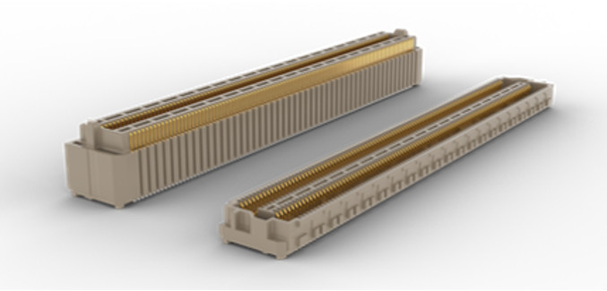
The array connector chosen for COM-HPC is an open flexible pin field, which means that all the pins are the same. Those pins can be defined as single-ended signals, differential pairs, and power; whatever fits your application best. Another feature of the COM-HPC connector is the BGA solid ball attach, which eases the solder flow to the PCB.
To mitigate crosstalk, the center row was separated by about 2.4 mm and the outer row by 2.2 mm. This small amount of spacing helps to mitigate crosstalk and allows for more ground vias. These features are key to attaining the 32-Gbit/s performance while easing the routing out of the connector pin field vertically or horizontally.
When it comes to the power pins on the connector, because there’s a finite number of pins, you want to reserve only what you’re likely to need. And the I/O pins provide for COM-HPC’s high bandwidth, so you want as many available as possible.
According to Burrell Best, Samtec’s Industry Standards Manager for the Signal Integrity Group and also the Chairman of the COM-HPC Signal Integrity (SI) subcommittee, “Once we got to the right number of power pins, we had to do a lot of testing and make a few changes. We did three iterations of the test before we ended up with a final footprint.”
The objective of the COM-HPC SI subgroup was to determine loss budgets for the high-speed interfaces. This work was completed in parallel with a smaller group of companies, chaired by Samtec. The work group built and shared models to ensure consistency. Then all the data was compiled and became the basis of the specification.
Best dives much deeper into the connector specification process in a video that provides an overview of the signal- and power-integrity subgroup activities. In addition, a host of other videos walk through other key parts of the COM-HPC specification.