How to Overcome the Power-Heat Dissipation Challenge in Embedded Motor Control Systems
February 01, 2021
Story
Power dissipation and thermal dissipation are an ongoing challenge for developers of embedded motor control systems, as the increasing deployment of actuators in cars, the drive to reduce engine CO2 emissions, and increasing vehicle weight have resulted in ever-increasing integration and performance density.
This article proposes a number of improvements in the motor control software and hardware environment, using a stepper motor actuator IC as an example, that aim to address these challenges.
In vehicles, motors and actuators are used in a wide range of applications from front grille shutters and adaptive headlights to door mirror adjusters. Motor control ICs, as the name suggests, control the performance of electric motors. These devices are evolving to integrate all the necessary functions, such as voltage regulators, oscillators, watchdogs, flash memory, EEPROM, ADC, phase current controls, and motor drivers. This high level of integration enables a compact and smart actuator design within a single chip. The downside, however, is that all these increases in integration and performance density create heat. In embedded motor control systems, where space is at a premium, engineers are reaching their limits in terms of power dissipation and thermal management. But this challenge is not unbeatable; specific measures can help solve the power-heat dissipation problem.
Establishing a Thermal Budget
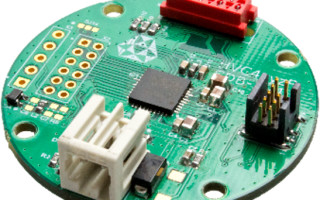
To establish the thermal budget, we examined a stepper motor actuator based on a TDK-Micronas HVC 4xyzF SDB-I v4.1 evaluation board, which uses a highly integrated motor control IC (figure 1). The board is similar to a real-life application in terms of its structure and size.

Figure 1: Block diagram of the stepper motor actuator
The basic requirements for operating the actuator are:

The maximum possible ambient temperature (TA) is calculated from the power dissipation to be expected in the IC (PV_IC), the thermal resistance between junction and ambient (RthJA) and the maximum permitted junction temperature (TJ). Here, the IC’s ambient temperature on the circuit board should be considered, i.e. without any housing, though there may be one present. As a worst-case scenario, maximum values are applied:

The total power dissipation converted in the IC is composed of the power dissipation from the motor drivers (PMotorDriver) as well as of the power dissipation of the CPU and peripheral modules of the IC (PDDP).
The motor driver losses are calculated from phase current (IPhase_RMS) and the integrated half-bridges’ output resistance. For each of the two motor phases, the resistance of a high-side (RDS(ON)hs), and a low-side transistor (RDS(ON)ls) are taken into consideration. The switching losses for one PWM modulated transistor are approximated.
The switching losses at 20 kHz PWM frequency, standard setting of the switching speed, and three PWM modulated transistors are represented by an additional power loss adder of 13%. For simplicity, we did not consider freewheeling losses separately. As a worst-case scenario consideration, the motor is operated continuously, i.e. the effective phase current flows continuously. The motor driver losses are thus calculated at:
The losses from the CPU and peripherals are determined from the current consumption of the IC (IDDP) and the given operating voltage (VBAT). For simplification, the voltage drop at any polarity protection that may be present is ignored, representing an additional safety margin.
With the help of the following datasheet maximum parameters, the maximum power dissipation is calculated:

This enables us to calculate the maximum motor losses:
In turn, we can then calculate the total power dissipation converted in the IC:
A simplified thermal model of the actuator (figure 2) shows that this is limited to the primary thermal resistances, which should be enough to consider the steady-state.

Figure 2: Simplified thermal model of the TDK HVC 4xyzF SDB-I v4.1 evaluation board
The starting point is a circuit board similar to the circular evaluation board (figure 3), made from FR4 material; it is 1.6 mm thick and has a diameter of 40 mm. It has two signal layers, a 35 µm copper layer, a 3 x 3 thermal via array and a copper surface on the bottom side below the ePad, which is of an approximated area of 0.75 cm2.

Figure 3. The TDK HVC 4xyzF SDB-I v4.1 evaluation board
This circuit board achieves an RthJA max. of approximately 32 K/W. Thus, we can calculate the maximum possible ambient temperature of the circuit board.
Usually, the circuit board and motor are positioned closely together in a housing. Therefore, to calculate the temperature within the housing, the motor’s power dissipation must also be taken into consideration. We used a plastic housing with a measured thermal resistance (RthAH) of 11 K/W.
The motor losses (PMotor) are only depicted through the copper losses, which constitute the majority of losses to keep things simple. The resistance of the motor phases, RPhase, is assumed to be 12 Ω. We can, therefore, calculate the power dissipation of the motor.
With this information, we can then calculate the total power dissipation (Ptot) in the housing.
The temperature gradient (ΔT) across the actuator housing is thus determined by:
If this temperature gradient is added to the actuator’s maximum specified ambient temperature (85°C), this results in an internal housing temperature of 116.4°C.
There is a gap of 10 K between the previously calculated maximum allowable ambient temperature of the circuit board (106.8°C), without motor and housing, and the housing’s internal temperature (116.4°C) which has now been determined. Appropriate action to close this gap, therefore, needs to be taken.
Use Only When Needed
The most effective way to reduce power dissipation is not to let it occur at all. All the peripheral modules, therefore, should only be active when required. By far, the most significant consumers of power in the evaluation board are the ADC (8 mA), BEMF-Comparator (1.3 mA), and Enhanced PWM (1.1 mA).
While the motor is running, the BEMFC and EPWM must be active to create a holding toque even during dwell times. In contrast, the ADC is not always required and, as it is the greatest consumer of power, a significant savings can be attained by ‘on demand’ operation.
In our stepper motor application, the ADC measures the back electromotive force voltage to identify overload and the step loss connected with it. Assuming the speed is 1000 full steps per second, the ADC is active 1000 times per second, or every millisecond. With a conversion time of 1 µs and the use of eight sequential conversions per event, and factoring in warm-up and synchronization times, results in a total ADC active time of 20 µs per full step.
Therefore, the average active time (TA) can be calculated as follows.
From this, we can calculate the average current consumption (IADC_av.) of the ADC.
The current consumption of the module can thus be lowered by 7.84 mA, which corresponds to a power dissipation reduction of 7.84 mA × 16 V = 125.4 mW.
Optimizing Clock Speed
In embedded actuators, software is generally event-controlled, where actions are triggered by interrupts. The CPU is mostly involved with background tasks and waiting for new events. These can be internal events, such as a timer interrupt, or external events, such as over- or under-voltage interrupts.
Dynamically slowing the CPU clock speed during non-time-critical background tasks reduces the current consumption. As soon as an interrupt arises, the CPU can automatically switch over to the maximum clock speed, and the interrupt service routine can be processed at maximum speed. At the end of the interrupt service routine, the software switches back to the lower clock speed.
For a typical stepper motor software, the CPU spends on average 40% of its time performing interrupt service routines. This means that 60% of the time is spent working on background tasks; slowing the clock speed during this time will significantly reduce the current consumption.
A good compromise is to choose a 5 MHz CPU clock speed for background tasks. A quarter of the maximum clock speed, which is 20 MHz, achieves a current saving of 38% (figure 4). The total current consumption (without motor drivers), therefore, is lowered by 60% × 38% = 22.8%.

Figure 4: Current consumption of the TDK HVC 4223F MCU standardized to 20 MHz. The line indicates current savings.
The typical current consumption of the HVC 4223F MCU, with all peripheral modules switched off (where fYS = fCPU = 20 MHz) is at 15 mA. Therefore, 15 mA × 22.8% = 3.42 mA can be saved. This saving corresponds to a power dissipation reduction 3.42mA × 16V = 54.72 mW.
Lowering Switching Losses
The switching losses in the motor drivers are caused by voltage, current, and switching time. As external requirements determine both voltage and current, only the switching time can be varied. Here, we can set the switching speeds in three stages. In the fastest setting, the switching time can be more than halved compared with the slowest setting. Reducing the switching losses adder from 13% to 5% of the motor driver losses are calculated.
As the original power consumption calculation was 0.791 W, this corresponds to a power dissipation reduction of 56 mW. However, please note that careful consideration towards the electromagnetic compatibility must be checked, as this staging technique could influence individual cases.
PCB Optimization
The ePad on the bottom of the QFN package (figure 5) takes the primary heat flow vertically. The heat must conduct from underneath the chip, through the circuit board to the bottom layer of the PCB. Therefore, it is essential to make the copper surface on the bottom layer as large as possible to ensure horizontal distribution and effective heat removal.

Figure 5: QFN40 package with exposed pad (ePad)
Because standard vias have the risk of solder outflow, we recommend that they are filled with resin and capped with copper. We also recommend using 4×4 or 5×5 via arrays. Any more will only lead to a small reduction of the thermal resistance (figure 6). If the demands on the mechanical stability permit it, you can also reduce the thickness of the circuit board, as the thermal resistance in the vertical direction is directly proportional to the circuit board thickness.

Figure 6: Rth of the vias standardized on 2×2 via
Further improvement in heat dissipation can be attained by maximizing the ground plane connected to the ePad. Through the layout optimization, the copper surface can be doubled to approximately 1.5 cm², which reduces the thermal resistance by 2 K/W. Compared with the original two-layer circuit board, which has a thermal resistance of 32 K/W, these optimizations reduce it down to 26 K/W.
If costs are not a concern, you can use a four-layer circuit board, which lowers the thermal resistance down to 20 K/W by connecting the ePad to additional interior layer ground planes.
It is also cheaper, but less effective, to double the copper layer thickness of the exterior layers to 70 µm, which gives a reduction of 1 to 2 K/W on this circuit board. However, if you do decide to take this option, do so at an early stage as the thicker copper layer impacts the layout of the signal layers. This is because the minimum track width and distances must almost be doubled, when doubling the copper thickness.
Maximum Headroom
By optimizing the software, the power dissipation of the IC could be reduced by 238.1 mW. Optimization measures on the circuit board reduces the thermal resistance (RthJA) by 6 K/W. With these new numbers, we can re-calculate the maximum permitted ambient temperature of the circuit board.
Through simple and cost-effective measures, a 14.2 K improvement could be attained compared with the initial permitted maximum ambient temperature of the circuit board of 106.8°C.
The new calculation of the temperature gradient along the housing with lowered power dissipation results in:
This corresponds to an improvement by 2.62 K compared with the initial temperature gradient of 31.36 K. Added to the required maximum ambient temperature of the actuator (85°C), the new internal housing temperature results in 113.7°C. This closes the gap, with a comfortable headroom of 7.3 K.
Conclusion
Using cost-effective optimizations to the software and the circuit board can improve an application’s thermal budget and give developers of embedded motor control systems plenty of headroom. Importantly, these improvements can be achieved on any embedded motor control system.
The TDK-Micronas HVC flex servo-drive family enables the cost-effective development of high-performance and compact embedded motor control systems. Powered by a 32-bit CPU (ARM Cortex-M3), they address the power-heat dissipation challenge. Besides the two-phase bipolar-stepper motor that we used in the calculation, the microcontroller, which integrates all the necessary functions, is equally suitable for brushless DC (BLDC) motors with up to three phases, and brushed DC (BDC) motors.
Andrew joined TDK-Micronas in 2010 as Automotive Sales manager for North America. Andrew has served in a variety of roles at several major semiconductor companies over the past 30 years. These roles include applications support, market development and sales. Andrew received a BSEE degree from Oakland University.