Make a Joule Thief: Three Inductor Options
March 24, 2023
Blog
Recently I’ve been considering how to run an LED for a really, really long time on a CR02032 battery, and eventually (re)stumbled upon the idea of a joule thief. The video below does a good job outlining how this circuit works.
Here I’ll discuss three options for building a joule thief, and in a follow-up, I’ll analyze how this device works with the help of a DSO1511G oscilloscope from ZEEWEII.
.png)
Standard joule thief schematic. [Image Credit: By Rowland - Own work, CC BY-SA 3.0, (https://commons.wikimedia.org/w/index.php?curid=31765405)]
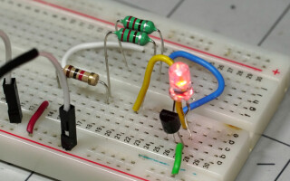
Toroid Joule Thief
For the typical joule thief, you’ll need the following:
- battery in the 1-2V range
- 1k resistor
- NPN transistor (2N2222 used here)
- LED
- ferrite coupled toroid inductor (2mH tested)
.jpg)
Toroid Joule Thief. (Image Credit: Jeremy Cook)
Wire your circuit as shown in the schematic and image above, and your LED should light up. Ensure the inductor lines are wired in such a way that current from the battery flows through each line in opposite directions. Pictured above is a purchased toroid-style inductor in the 2mH range, which lights the LED brightly under power of a 1.5V AAA battery. You can also wind your own toroid inductor if you so desire.
Axial Inductor Joule Thief
Axial inductor Joule Thief circuit, powered by a single AAA battery. Inductors need to be directly adjacent for circuit to work: pic.twitter.com/MJk2PayZPs
— Jeremy Cook 🤖 (@JeremySCook) March 20, 2023
Obtain the first four elements of this design listed above, and for the fifth, substitute in:
- 2 axial toroid inductors
Using a pair of side-by side axial inductors, my circuit experienced intermittent results using 1mH and 2.2mH values, while a 4.7mH device barely worked. Two 220uH inductors worked well. It seems that bigger isn’t always better in this case.
The inductors need to be positioned side by side, and here are wired so current to and from each lead is externally flowing in the same direction. The coils are internally wrapped in such a way that the current and magnetic flux of each component opposes the other in this orientation. The internals of such a device are pictured in the video above.
PCB Inductor Joule Thief
.jpg)
Standard joule thief schematic. (Image Credit: Jeremy Cook)
Again, use the first four elements of the standard joule thief, but substitute in the following:
- (possibly) somewhat higher value resistor
- PCB coil inductor
This idea was inspired in part by the PCB joule thief flasher seen here. In my initial testing, a 1-inch (~25.4mm) coil, similar to the device linked, worked quite well. My 18.6mm coil worked only intermittently, and neither the 13.1mm design, nor traces on the front and back of the .8mm PCB worked at all. As with the traditional toroid inductor design, the coils need to be wired in opposite directions with respect to the battery’s positive terminal.
Later testing with the 1-inch coil design yielded intermittent results, and I subbed in a 1.8 kOhm resistor to get it to work. Testing the coil with an inductance meter reads only around -.008mH of inductance. I’m not certain how it calculates a negative value here, but while it does recognize some sort of inductance, it’s at the extreme lower end of what my device can measure. It’s an interesting concept, but this coil design seems to be at the extreme low end of what’s needed inductance-wise.
Next Up: Joule Thief Analysis
In a second joule thief article, I’ll be using the ZEEWEII DSO1511G scope to further analyze what’s going on in this type of circuit. Until then, check out the video below by GreatScott! where he analyzes such a circuit, noting that it’s difficult to master this circuit design. While I don’t expect to produce a better analysis than ‘Scott! does there, we’ll also get another look at the ZEEWEII’s capabilities.