Testing and Analyzing the Success of your Robot Navigation System
February 17, 2022
Blog
If you’re designing a robot navigation system, for example for an autonomous vacuum cleaner, then it’s important that it can find its way around accurately. After you have decided on the right sensors, and put your system together, then testing is necessary to prove the navigation algorithms and ensure consistent high performance.
But how do you go about conducting this testing, and measuring performance?
In the case of a ground-roving robot, its localization algorithm must accurately track its location, while other algorithms help it achieve its larger function. The algorithms designed for navigation and those fulfilling a robot’s objective are meaningless without proper direction.
This is especially true of a cleaning robot that needs to cover an entire surface to finish its job. The more accurate its mapping, the faster it finishes its job, and the happier the end user. The same principle applies to any ground-roving robot: for instance, accurate movement from a large warehouse’s robots means that customers are getting their products that much faster, thus improving efficiency.
Since wheeled robots tend to move in straight lines, heading accuracy and heading drift (how heading errors change over time) are important metrics. While heading is a component of where the robot is going, it’s where it actually ends up that is most important. Measuring trajectory error, or how far away from the desired end point our robot reaches, will help us understand how accurate our system really is.
The Test Environment
In this example, we have chosen heading and trajectory error as the two most important criteria we are going to investigate. Now, we need a reference point, or truth, to compare to our robot’s outputs. To achieve this by tracking the robot’s motion, an IR-based camera system can provide flexibility, accuracy, and precision. IR-based camera systems are the same technology used for movie motion capture and in robotics labs around the world.

Figure 1: Robot motion capture.
The robot should be tested under conditions like its intended deployment environment – whether that is a mock warehouse, mock hospital, or mock living room. Environments vary in many ways, such as room sizes, where objects are located, changes in flooring, magnetic fields, and temperature. Ensuring that your test environment can cover these types of changes builds a more robust solution.
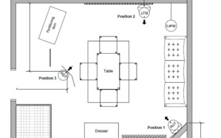
For example, CEVA’s robot vacuum testing is done in a mock living room based on an international standard. This standard is highly specific, and contains multiple pieces of furniture, changes in flooring, inclines, bumps, and even requirements for what is on the walls (which is relevant for VSLAM robots). By using this set of obstacles and settings, we can collect heading and trajectory data for the same scenarios that would be seen during use.

Figure 2: Robot vacuum test room.
Keep It Real
Our testing needs to investigate what happens when we change the environment in a way similar to the real world. For example, we know that heading errors are introduced due to inaccuracies in inertial sensors caused by temperature changes. We should then verify the operation of our robot across its expected temperature range.
In contrast to our well-organized test environment, we know that the real world is messy. Our robot will frequently be affected by unexpected changes: people or animals will bump into it, there may be other obstacles not in our test set-up, or the flooring material may be unexpected.
Testing needs to reflect these scenarios to be robust. The more iterations, the more complete our picture, and the better we can adjust our algorithms to improve system performance.
For example, we might include the following tests:
- Baseline – changing temperatures within expected range inside the test environment
- Bump – adding sudden orientation change or displacement to emulate incidental bumps
- Obstacles – increasing the number of objects and disruptions
- Longevity – increasing testing run-time to emulate use in an industrial setting
Ideally, we should run each of these tests multiple times on multiple testing platforms, to gather as much data as possible. This is obviously more costly and complex if you are testing the whole robot.
With our focus on sensors, CEVA tests multiple sensors riding on the same robot to get as much data as possible. This allows us to track heading relative to truth with multiple data points and gain more insight into how the base and outside factors affect their performance.
Analyze This
Data is nothing without the proper analysis, and with careful curation we can optimize our robot’s tracking performance. For instance, with our comprehensive test plan, we can look at how fast the robot’s perceived heading is drifting away from the heading measured by our motion capture system.
You can miss valuable insights if you only summarize heading accuracy with a few numbers (like the heading difference at the end of each trial), because sometimes there can be large errors that are later cancelled out by other large errors, or maybe one test was mostly accurate except for a brief glitch at the end.
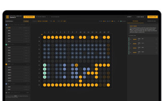
So, instead, we examine the error growth rate at each moment in time (for example, over a rolling 15-second window) and treat each of these as a separate data point. Then we plot the distribution of these error growth values for each trial in a CDF (Cumulative Distribution Function) as seen in Figure 3. Looking at the plot (lines closer to the left are better here), we can easily compare the median performance versus the worst case or other percentile, and identify outliers.

Figure 3: CDF of multiple algorithms over different conditions.
This helps us determine which sensors and algorithms run with less heading drift than others and show us how to adjust the values for higher accuracy.
We can perform a similar analysis while looking at trajectory error. It can be measured in several ways:
- Absolute error compares the end points of the perceived and actual trajectories independently. This allows us to see the accumulation of heading and distance error over a long trial.
- Relative error adjusts the two datasets to the same starting point over each measurement window. This isolates the accumulation of previous errors from the error growth arising from heading error.
- Reoriented relative error accounts for translation and rotation differences at the start of each measurement window. This isolates the overall error growth per unit distance from previously accumulated errors. This is the most useful metric for identifying the source of trajectory errors, which appear as “hot spots” in the reoriented relative error.
Conclusions
Designing and testing a robot navigation system may seem like a difficult task, but by breaking it down into its constituent parts, it becomes more manageable. With the right sensors, and the right software to combine their data, the robot can be as accurate as possible within the project specifications.
The testing approach described in this article can be used to determine the accuracy of a robot, and its behavior under typical real-world conditions. By testing in a suitable environment, and analyzing the test data appropriately, we can ensure that the finished robot behaves as expected, whatever conditions it encounters.
If this process sounds overly complex for dealing with the sensors of your robot, CEVA’s ‘Navigating the Complexities of Robotic Mapping White Paper’ provides a useful guide to help you gain more confidence. It highlights issues to think about when designing a sensor system for robots: how to get the best sensors, make the right test plan, collect data, and find insight in the analysis, so that a suitable sensor system can be designed for any ground-moving robots. To download a copy of the whitepaper, visit https://www.ceva-dsp.com/resource/navigating-the-complexities-of-robotic-mapping-whitepaper/.
Charles Pao started at CEVA Hillcrest Labs after graduating from Johns Hopkins University with a Master of Science degree in electrical engineering. He started work in software development, creating a black box system for evaluating motion characteristics. With a passion for media and communications, Charles started producing demo and product videos for Hillcrest Labs. This passion led to an official position transfer into Marketing. Currently, he is Hillcrest’s first point of contact for information and support and manages their marketing efforts. He’s also held various account and project management roles. Charles also earned Bachelor of Science degrees in electrical engineering and computer engineering from Johns Hopkins University.