KiCad 6 Align, Distribute, and Array Functions for Massive Time Savings
November 16, 2022
Blog
Placing components in the KiCad 6 PCB editor is fairly easy in a broad sense. If you have your grid set correctly, and enough space, getting things roughly in place and connected is fairly trivial. However, what if you need to place a number of footprints in a line, or need to make a grid of vias? Placing each one individually can be tedious, so for these tasks use the align, distribute, and array commands to save a massive amount of time and frustration!
KiCad 6 Align!

To use the align tool, first insert your footprints, graphics, edge cuts, etc. roughly in place on your PCB editor. Select the items that need to be aligned, right-click, and navigate to the Align/Distribute submenu. Here you’re presented with a number of choices: left, center, and right for horizontal alignment; and top, center, and bottom for vertical.
These horizontal/vertical options relate to the edges of each item, not the overall combined geometry. This is easy to see with differently sized objects, but they effectively make no difference if all the objects are the same. However, if you’re over an object when you right-click to perform the alignment operation, it will use that object as the reference. It stays in position, while everything else falls in line.
KiCAD 6 Distribute!

(Caption: Aligned to bottom, distributed horizontally)
Once you have your items in-line, return to the Align/Distrtibute submenu to space them out. Choose the vertical option to create an even vertical spacing between each selected element, and the horizontal option to space things horizontally. Both can be used one after the other to produce perfectly spaced angular distributions.
KiCad 6 Array!

(A staggered grid array, Image Credit: Screencap)
To create an array in KiCad 6, select the thing(s) you’d like to use as the array source, then right-click, this time selecting Special Tools and Create Array. Here you’re presented with a number of horizontal array options, such as the horizontal and vertical count and spacing. You can also set a row or column stagger value to have it produce an offset grid pattern, which can be especially useful for stitching layers together with vias, or for producing board graphics.
There’s also an option to produce a circular array. While likely much less used than its grid orientation cousin, it certainly has its place. Perhaps one might use it for graphics, or for a specialized via stitching arrangement.
Other Options? More Tips?

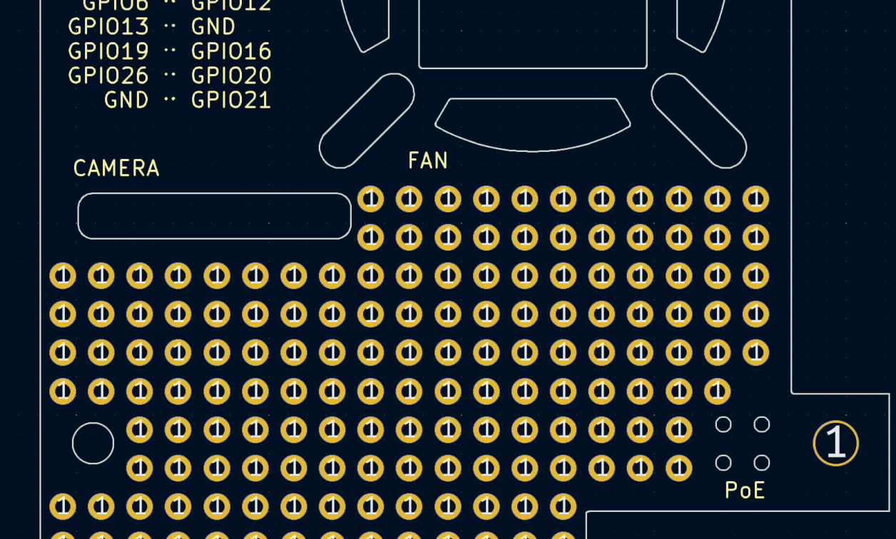
(Caption: A nice grid of through holes, as outlined in this PCB prototyping enclosure post, Image Credit: Jeremy Cook)
At the end of the day, if you need to create complicated artwork or cutout patterns, you may be better served using a more capable tool and importing graphics as a DXF. Notably, arrays can’t be parametrically edited in KiCad. If you want to make changes, you’ll have to instead undo your work and start over each time. Depending on the frequency, this can be no big deal or a huge annoyance.
For arrangement of actual footprints, off-the-cuff graphics needs, or any number of other functions, these simple tools can save you a huge amount of hassle. For additional KiCad layout techniques, check out my first quick tips post here, along with the more tips and techniques followup.
If something seems repetitive and tedious in KiCad, there’s often a better way to perform a task if you just know where to look. If you’d like a visual on this KiCad array/alignment functionality, Chris Gammell demonstrates it in the video below. He’s using KiCad 5.0, so there are a few subtle differences between that and the current KiCad 6.0 version:
Jeremy Cook is a freelance tech journalist and engineering consultant with over 10 years of factory automation experience. An avid maker and experimenter, you can follow him on Twitter, or see his electromechanical exploits on the Jeremy Cook YouTube Channel!