KiCad PCB Layout Quick Tips
December 10, 2021
Blog

Throughout the last year-plus, I’ve written a number of articles outlining my experience with KiCad. It’s an incredible open-source EDA package, and what I consider my first and best piece of advice for those getting started is to go ahead and order your first PCB when it seems workable. It may not be perfect, but you’ll certainly be able to improve things on the next run.
While other articles focus on larger concepts like working with footprints, and managing libraries, in this post I’ll outline several quick tips and tricks that can facilitate your PCB design process:
User Origin (dx/dy)
You will coordinate with respect to this origin point in the bottom right of the window as dx and dy (symbols that you may remember to represent change in x/y from calculus). Hit the spacebar at any point on your grid, and you’ll generate a new 0,0 point for this user origin. This can be a great reference when you need to position parts relative to each other.
Absolute coordinates are seen to the left of the user coordinates, with a 0,0 point referenced to the upper-left corner of your drawing. Next to that is a Z value, which corresponds to the zoom (not depth in the third dimension). Per my very rough “calculations” below, the on-screen image at Z 1.00 does indeed correspond to what will be produced in real life.

Chris Gammell discusses some for the finer points of different origin systems in the video below. He also shows how there’s a difference between hitting m for move and cmd-m, the later of which which presents you with several options:
Automatic Horizontal, Vertical, and 45º Lines
If you need to make vertical or horizontal graphic lines, one technique is to hit the spacebar at the line’s origin. You can then ensure that dx is zero for horizontal lines, and dy is zero for vertical lines. An easier way to accomplish this is to hold down the cmd key while forming the line, which will restrict graphical lines to either horizontal, vertical, or 45º angles.
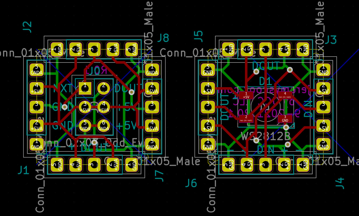
Keep in mind that you can use cmd-c to copy selected lines and/or components, and cmd-v to past them. With thoughtful selection of the base point, you can create interesting patterns like the hatching shown below, with minimal fuss. Also note that you can turn on this restriction be default under KiCad > Preferences > Pcbnew by checking Limit graphic lines to H, V and 45 degrees.
If you use the cmd/ctrl key when routing tracks, it will restrict them to a horizontal or vertical orientation.

Object Selection: Window or Crossing
To select multiple objects in Pcbnew, click and hold down the left mouse button, drag the selection window over the objects you’d like to select, and finally release the mouse button. If this selection is made from left-to-right, only objects entirely enclosed in this window will be selected. If done from right-to-left every object that is even partially within the window will be selected.
In AutoCAD, these techniques are known as either window selections (entirely enclosed) or crossing selections (all objects). It appears that KiCad has decided to follow this paradigm, which is great in my opinion. Perhaps this concept will be obvious to some, but I didn’t explicitly understand it in the AutoCAD realm until someone else pointed it out.
Little Tips, Big Difference
Some of these tips may seem simple, and perhaps even obvious. They’re the kind of thing that gets passed around a physical office without much thought, but for better or worse, many of us are working from home.
If a technique saves you a few seconds many times in a day, it’s well worth trying out something new. As one commenter put it in the Contextual Electronics video, “Didn't know the use of the space bar! that changed my life...” Sometimes techniques will only be obvious after you’ve seen them in use!
Note that cmd is listed in the article, as I use MacOS. This should be equivalent to ctrl in other systems.
Jeremy Cook is a freelance tech journalist and engineering consultant with over 10 years of factory automation experience. An avid maker and experimenter, you can follow him on Twitter, or see his electromechanical exploits on the Jeremy Cook YouTube Channel!


