Using FreeRTOS with the Raspberry Pi Pico: Part 2
October 31, 2022
Blog
This is the second blog in the series where we explore writing embedded applications for the Raspberry Pi Pico using FreeRTOS.
In this blog, we will cover how and when the FreeRTOS Scheduler decides which task to run. We will also build on our code example from the first blog to demonstrate Queues and Message Buffers, which are features of FreeRTOS. Finally, we will briefly touch on event-driven design. So, get your compilers ready, here we go.
In the first blog, we created a task with xTaskCreate() and started the Scheduler with vTaskStartScheduler(). Then, the task function we defined called vBlinkTask() was executed. This is a simple example of the Scheduler managing a single task. But, what happens when we create multiple tasks to run in our application? After all, that is the main point of multitasking. In the next section, we will dive deeper into the fundamentals of scheduling and tasks.
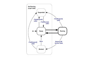
The Scheduler in FreeRTOS implements a scheduling algorithm to determine what task should run at what time. For scheduling, time is determined by what is known as a “tick.” The time between ticks depends on the hardware clock speed and configuration, but is generally between 1-10 milliseconds based on the timing needs of the application. The time between ticks is known as a “time slice.” In its default configuration, FreeRTOS uses a scheduling policy where it will switch between tasks that are the same priority in round-robin order on each tick, and task execution happens within a time slice. The priority of a task is set at creation time, which we saw in the code example from the first blog as an argument passed to xTaskCreate() with a value of 1. However, this can be changed at runtime with vTaskPrioritySet(). Also, the scheduling policy is “preemptive,” meaning that the Scheduler will always run the highest priority task that is available to run. So, if a higher priority task becomes available to run while a lower priority task is already running, the Scheduler will start the higher priority task, causing the lower priority task to be immediately preempted. The following diagram illustrates the full task state machine, including the task states and transitions. When a task is executing, it is in the “running” state. When a task is not executing, it is in the “suspended,” “blocked,” or “ready” state.

Given the mechanics above around scheduling, there are a couple of points worth noting. First, because the Scheduler uses a preemptive scheduling policy, a high priority task that is never “blocked” or “suspended” can “starve” any lower priority tasks from ever executing. Task starvation can be avoided with techniques like event-driven design, which we will discuss later. Second, the scheduling policy described above holds true for a single core system. However, multiple cores add another dimension to how the Scheduler may behave, because with multiple cores tasks are able to run not only serially but also concurrently. This is especially relevant for the Raspberry Pi Pico as it has a dual core M0+ processor, and FreeRTOS can take advantage of this multicore capability with symmetric multiprocessing (SMP). SMP will be covered in more detail later in this blog series, but keep this in mind when considering Scheduler behavior.
Now that we understand how tasks are managed by the Scheduler, let’s look at how tasks can communicate with each other. This concept is known as inter-task communication. To accomplish this, we can use other built-in features of FreeRTOS such as Queues, Stream Buffers, and Message Buffers. Below is a code example using a Queue. In this example, one task determines how many LED blinks to perform while the other task executes the number of blinks based on the value from the queue. Rename the existing “main.c” file from the example in the first blog and create a new “main.c” file, adding the block of code below. Then, follow the instructions from the first blog to build and flash the application to the Raspberry Pi Pico.
#include "pico/stdlib.h"
#include "FreeRTOS.h"
#include "task.h"
#include "queue.h"
QueueHandle_t blinkQueue;
void vBlinkReceiverTask() {
for (;;) {
int blinks = 0;
if (xQueueReceive(blinkQueue, &blinks, 0) == pdPASS) {
for (int i = 0; i < blinks; i++) {
gpio_put(PICO_DEFAULT_LED_PIN, 1);
vTaskDelay(200);
gpio_put(PICO_DEFAULT_LED_PIN, 0);
vTaskDelay(200);
}
}
}
}
void vBlinkSenderTask() {
int loops = 4;
for (;;) {
for (int i = 1; i <= loops; i++) {
xQueueSend(blinkQueue, &i, 0);
vTaskDelay(500 + (i * 500));
}
}
}
void main() {
gpio_init(PICO_DEFAULT_LED_PIN);
gpio_set_dir(PICO_DEFAULT_LED_PIN, GPIO_OUT);
blinkQueue = xQueueCreate(1, sizeof(int));
xTaskCreate(vBlinkSenderTask, "Blink Sender", 128, NULL, 1, NULL);
xTaskCreate(vBlinkReceiverTask, "Blink Receiver", 128, NULL, 1, NULL);
vTaskStartScheduler();
}
Running the example above, you should see a blink sequence on the LED of 1, 2, 3, and 4 short blinks which then repeats. The Queue, “blinkQueue,” is dynamically allocated to hold integer values. Queues can be dynamically allocated from the heap, or statically allocated at compile time. Queues in FreeRTOS use the copy method, so values sent to the queue are copied byte for byte. That enables queues to pass data across memory boundaries, and pointers to data to be queued when the data is large. Beyond our simple example, there is a rich API for Queue Management that you can explore and experiment with further.
As mentioned earlier, other options available with FreeRTOS for communicating between tasks include using a Stream Buffer or a Message Buffer. A Message Buffer is a type of Stream Buffer and below is a simple example of Message Buffer usage. For this example, the “CMakeLists.txt” file in our project folder must be modified to enable output which can be read from the USB serial port. Add the following lines to the end of your “CMakeLists.txt” file:
# enable usb output, disable uart output
pico_enable_stdio_usb(blink 1)
pico_enable_stdio_uart(blink 0)
Once the “CMakeLists.txt” file has been modified, rename the existing “main.c” file again and create a new “main.c” file with the following contents:
#include <string.h>
#include <stdio.h>
#include <stdlib.h>
#include "pico/stdlib.h"
#include "FreeRTOS.h"
#include "task.h"
#include "message_buffer.h"
const size_t BUFFER_SIZE = 32;
void vReceiverTask(void *pvParameters) {
MessageBufferHandle_t buffer = (MessageBufferHandle_t) pvParameters;
size_t messageSize = BUFFER_SIZE - 4;
char *message = malloc(messageSize);
memset(message, '\0', messageSize);
size_t lengthReceived;
for (;;) {
lengthReceived = xMessageBufferReceive(buffer, (void *)message, BUFFER_SIZE, 0);
if (lengthReceived > 0) {
printf("length: %d, message: %s\n", lengthReceived, message);
memset(message, '\0', messageSize);
}
}
}
void vSenderTask(void *pvParameters) {
MessageBufferHandle_t buffer = (MessageBufferHandle_t) pvParameters;
char message[] = "FreeRTOS + Pi Pico";
for (;;) {
xMessageBufferSend(buffer, (void *)message, strlen(message), 0);
vTaskDelay(1000);
}
}
void main() {
stdio_init_all();
busy_wait_ms(1000);
MessageBufferHandle_t buffer = xMessageBufferCreate(BUFFER_SIZE);
xTaskCreate(vSenderTask, "Sender", 128, (void *)buffer, 1, NULL);
xTaskCreate(vReceiverTask, "Receiver", 128, (void *)buffer, 1, NULL);
vTaskStartScheduler();
}
Follow the build and flash procedure used from the first blog and the example earlier to run the code. Then, launch an application that can read output from the Raspberry Pi Pico over the USB serial port. There are a number of ways to do this depending on your environment. For Windows, tools like PuTTY or Tera Term are good examples. On MacOS, “screen” will do nicely. On Linux, you can use “minicom” or even the pySerial “miniterm” tool. In all cases you will need to find the port that USB serial is connecting to on your computer and configure your tool with that port to display the output.
You should now see the following output if everything is working correctly: “length: 18, message: FreeRTOS + Pi Pico”. You might notice the allocated message size was created 4 bytes less than the allocated buffer size in the code. This is because the Message Buffer uses 4 bytes to store the message length. Remember to account for this when using Message Buffer. Like Queues, Stream Buffers and Message Buffers have extensive APIs that you can explore and experiment with further.
Congratulations, you have now used two different methods for inter-task communication with FreeRTOS on the Raspberry Pi Pico. You may have noticed something similar about both methods demonstrated. In each code example, the receiver task sits in an infinite loop while checking to see if data was received. If you recall the point made earlier in this blog about the preemptive scheduling policy and task starvation, you might recognize that this existing design could lead to a problematic situation if we introduce other tasks with different priorities or change the priority of our sender or receiver task. Furthermore, resources like processor cycles could be better optimized. Taking these points into consideration, we should consider moving toward an event-driven design for our application so that tasks only run when key events occur. The next blog in this series will cover precisely that and more.

Daniel Gross is a Senior Developer Advocate at Amazon Web Services (AWS). Focused on FreeRTOS and embedded devices interacting with cloud services, Daniel is passionate about delivering a great developer experience for IoT builders.