Design of FMCW radars for active safety applications
May 05, 2017
Story

Car manufacturers, automotive electronics suppliers, and universities are working to develop new electronic systems for advanced driver assistance sys...
The following shows a unique tool chain for modeling and simulating a complete 77 GHz FMCW radar system, including waveform generation, antenna characterization, channel interference and noise, and digital signal processing (DSP) algorithms for range and speed determination. Simulation and modeling of RF impairments such as noise, nonlinearity, and frequency dependencies enable us to test the behavior of “off the shelf” components described with datasheet parameters, and provide information about the performance achievable with a specific component configuration and related costs.
Frequency-modulated continuous waveform (FMCW) radars are becoming increasingly popular, especially in automotive applications such as adaptive cruise control (ACC). The transmitter of an FMCW system sends a chirp signal with high frequency and large bandwidth. The transmitted signal hits the target and is reflected back toward the receivers with a time delay and a frequency shift that depends on the target distance and relative speed.
By mixing the transmitted and the received signal, the time delay corresponds to a frequency difference that generates a beat frequency. This allows a very accurate and reliable estimation of the target distance[1]. Often, multiple antennas are used for spatial processing and beamforming to make the detection more reliable or to have a directional system, as depicted in Figure 1.
|
|

In the design, modeling, and simulation of an FMCW radar, the designer must take into account more than just the nominal behavior. After using the radar equation to determine the fundamental design parameters, the designer must analyze the impact of imperfections introduced by the RF front-end. Nonlinearity, noise, frequency selectivity, and mismatches between components operating over ultra-large bandwidth reduce the actual dynamic range of the detectable signal.
By accurately modeling the RF front-end, designers can make complexity tradeoffs between the hardware architecture and the digital signal processing algorithms. Moreover, they can assess whether previous implementations can be reused to retarget the radar for augmented specifications, or whether off-the-shelf components can be directly used for the front-end implementation.
Determination of FMCW waveform
The first problem we have to cope with when designing a new radar system is to determine the parameters of the triangular chirp waveform in order to achieve desired resolution with the specified range. We consider an automotive long-range radar used for automatic cruise control, which usually occupies the band around 77 GHz[2, 3].
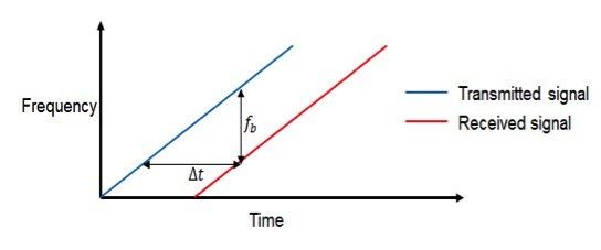
As shown in Figure 2, the received signal is an attenuated and time-delayed copy of the transmitted signal where the delay Δt is related to the distance of the target. Because the signal is always sweeping through a frequency band, at any moment during the sweep, the frequency difference fb, usually called beat frequency, between the transmitted signal and the received signal is constant. Because the sweep is linear, one can derive the time delay from the beat frequency and then the distance of the target from the time delay.
|
|
Using MATLAB and Phased Array System Toolbox functionality, we can easily determine the fundamental waveform parameters for a radar working at 77 GHz, such as sweep bandwidth and slop, maximum beat frequency, and sample frequency based on user-specified range resolution and maximum speed as shown in Figure 3.
|
|

Modeling RF components, noise, and nonlinearity
Once the chirp parameters have been determined, we can proceed with modeling the transceiver of the radar system.
The front-end of the radar system includes the transmitter, the receiver, and the antenna. These models are provided in the toolbox. We parameterize these models with desired values, such as phase noise and thermal noise. Alternatively, we can model the transmitter and receiver using RF components provided in Simulink using SimRF to model the effect of component-level noise, nonlinearity, and frequency selection. Figure 4 shows how we have modeled the RF front-end using SimRF blocks. This library provides a circuit envelope solver for the rapid simulation of RF systems and components such as amplifiers, mixers, and S-parameter blocks.
|
|

We can describe in detail the architecture of the transceiver and use datasheet parameters for each front-end element. Taking as an example the direct conversion I/Q mixer, we have modeled it as illustrated in Figure 5. This element demodulates the received signal, multiplying it with the originally transmitted waveform.
|
|

Parameters of the two multipliers used in the I/Q mixer have been set directly on the blocks or using workspace variables.
With this configuration, it is easy to try different setups and explore design spaces by using different datasheet parameters for simulating off-the-shelf components.
Complete system simulation
After all components of the radar system have been properly parameterized, we can proceed with a complete desktop simulation to test whether the system will work properly under different test conditions.
When running this simulation, the model not only provides the estimated values of relative speed and object distance, but also visualizes the spectrum of transmitted and received signals, as shown in Figure 6.
|
|

A first simulation running under ideal conditions (absence of noise and distortion) shows that speed and position can be detected correctly for all targets in use. This simulation validates the test environment and the DSP algorithms. For subsequent simulations with added transceiver nonlinearity and noise, the radar deviates from the ideal behavior and cannot detect cars when they are far away.
After increasing the isolation of the mixer and the gain of the power amplifier, the radar system extends the detection range, and the simulation once again correctly estimates the target speed and range.
It is necessary to carefully trade off the gain of the different stages in order to avoid having the receiver operating in saturation. This model allowed us to simulate using a different set of parameters. It also helped us to select the suitable components for the radar implementation and to verify their impact on the radar performance.
Conclusion
This article has covered the modeling and simulation of a complete FMCW radar system for automotive active safety applications using a MATLAB-based tool chain. The proposed workflow allows us to simulate RF components within a complete system-level model, including digital signal processing algorithms. This approach reduces both the time needed for radar development and the complexity of system tests, making the development cycle less costly.
To learn more, see Phased Array System Toolbox at se.mathworks.com/products/phased-array.
MathWorks
References:
1. Design and Verify RF Transceivers for Radar Systems. Giorgia Zucchelli, MathWorks. mathworks.com/videos/design-and-verify-rf-transceivers-for-radar-systems-81990.html.
2. Automotive Adaptive Cruise Control Using FMCW Technology. mathworks.com/help/phased/examples/automotive-adaptive-cruise-control-using-fmcw-technology.html.
3. Karnfelt, C., et al. 77 GHz ACC Radar Simulation Platform, IEEE International Conferences on Intelligent Transport Systems Telecommunications (ITST), 2009.