Thermal management techniques extend automotive ECU's reliability
July 13, 2015

It's ironic, when you think about it. Jack Kilby, inventor of the first integrated circuit, was driven to do so, in part, to find a way to replace the...
It’s ironic, when you think about it. Jack Kilby, inventor of the first integrated circuit, was driven to do so, in part, to find a way to replace the heat-generating vacuum tubes in use at the time. The heat problem “solved,” his invention would go on to be the foundation upon which the electronics industry would grow.
Now, as we head into a new era of pervasive automotive electronics, we need to turn once again to the fundamental problem of heat, this time to protect those very electronic ICs and systems Kilby helped propagate. The challenge now is to mitigate the effects of extreme temperatures and thermal cycling under the hood.

Figure 1: The first IC was invented by Jack Kilby in 1958, in part as way to remove the miniature heaters (aka: vacuum tubes) that performed the switching function now performed by transistors. Ironically, Kilby’s invention became so prolific, and with such density and ubiquitous applicability, we’re back to managing heat, again at the materials level.
For components and ICs, designers put a lot of effort into selecting those that are most appropriate for the automotive electronic control unit (ECU) being developed. That ECU could be a chassis and safety control unit, and engine control unit, or even a monitoring and communications gateway unit. Regardless of the ECU, designers select the components, derate them appropriately for their design calculations, and then expect them to last the 10 to 15 years an automobile may be operated. Job done.
Not quite. The components might operate fine, but only if they’re placed on a PCB that has been engineered from the ground up to maintain its structural integrity within the automobile’s extreme thermal and vibrational environment.
Printed circuit boards (PCBs, or printed wiring boards (PWBs)), have for decades been the most common means of connecting components of an electronic system such as resistors, integrated circuits, capacitors, connectors and inductors.
Their basic structure hasn’t changed much, comprising layers of glass cloth (prepreg) that have been impregnated with epoxy resin, upon which copper or aluminum traces are laid out. These traces connect to the various layers using vias, blind vias and inner vias, and connect the components as well as their signal, power and ground planes.
As the serving platter for electronics for many years, the PWB’s mechanical stresses due to vibration have been well documented. Strengthen attachment points and ensure sufficient rigidity and it’s pretty much good to go.
With heat, however, the differing coefficients of thermal expansion (CTE) between the resin materials (CTE of 30 to 40) and the metal layers and vias (CTE of 18, for copper) can play havoc, potentially stressing and cracking the conductors if the right materials and structure aren’t used in the PWB’s construction.
For sure, the use of prepreg constrains the CTE of the resin material in the x-y axis, but the resin must still expand, so it does so in the z axis, hence the focus on CTEz as it is the significant variable.
However, another factor to be considered is the glass transition temperature, Tg. Above the Tg, the material rate of expansion increases, potentially reaching a CTE of 400.
Add in RoHS lead-free-solder requirements, with the resultant high-temperature reflow solder temperatures, and it’s clearly a case of back to basics for cutting-edge PWB-based thermal management for reliable ECUs.
Basic materials, that is. Along with their construction. That’s how metal-clad substrates (MCSs) came about. MCSs are thermally conductive base materials for temperature-sensitive applications. The combination of a copper-clad dielectric and an aluminum carrier delivers effective heat dissipation and provide an alternative to active cooling methods and thick-film techniques. In addition to its high thermal conductivity, MCS, including the material provided by Isola, provides very high thermal and mechanical reliability.
Different dielectrics can be selected to create the ideal MCS for each application. For these “lambda materials,” DE104, IS410, 370HR or IS450, prepreg can be used as part of the modular configuration. These prepreg systems have thermal conductivities between 0.23 (DE104) and 1.0 W/m*K (IS450). The high-Tg epoxy system of IS450 can be modified, by using a special filler, to obtain a higher thermal conductivity compared to standard systems.
Based on the configuration of the MCS construction and its efficient heat dissipation, construction pitches can be reduced and increased power density can be achieved, allowing for smaller assemblies that are hard to realize with conventional base materials.
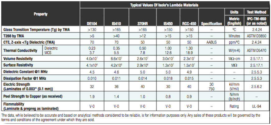
Figure 2: Metal-clad substrates etch the copper foil into the desired circuit pattern on the PWB (or PCB) and the metal base draws heat away from the circuit through the thin prepreg. The prepreg uses proprietary resin to achieve higher thermal conductivity than standard FR4. (Click image to enlarge)
Along with automotive ECUs, other applications of MCS include high-power LED modules, converters, heat-sink circuits and industrial electronics.