Getting Started With a 128x64 Pixel SSD1306 OLED Display
July 12, 2021
Blog
If you have browsed online auction sites and/or various small electronics projects to any extent, there’s a good chance you have come across a .96” 128x64 pixel OLED display, based on the SSD1306 driver.
These devices are incredibly small and are even appropriate for a DIY smartwatch or any number of handheld applications. After buying a few some time ago, I decided it was time to fish them out of the parts bin and get a few of them working using an Arduino Uno.
While not extremely complicated, there is a bit of a learning curve to using these devices. Adafruit, which offers their own version, wrote the libraries that I will be using here, and does a nice job of documenting how to use them. In this post I will go over the very basics of setting up a non-Adafruit SSD1306 128x64 pixel display, largely using text as the output method. The basic procedure should be applicable to Adafruit’s OLED as well.
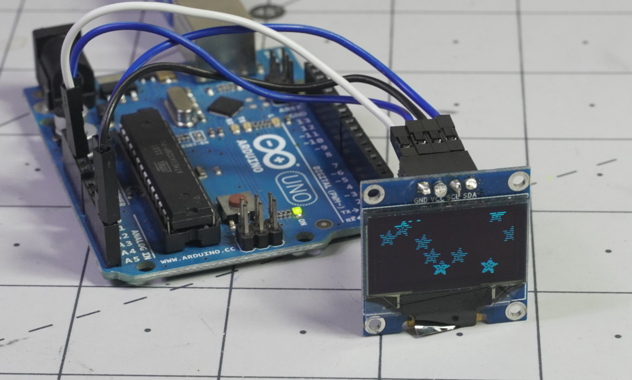
Wire the Display

Image Credit: Jeremy Cook
The SSD1306 controller for these little boards can communicate via I2C and SPI, however, the units I had available are set up for I2C communication. This is all well and good as I am more familiar with this technology.
To connect an Arduino Uno to this I2C device, make the following connections:
• VCC – 5V
• GND - GND
• SDA - A4
• SCL – A5
• Pull-up resistors – Connect the SDC and SCL pins to +VCC via a 10K ohm (or other large value) resistor. The screen may work without them, but it is a good idea to have pull-ups on the I2C bus.
If available, you will also want to check if the board is 5V tolerant, as the SSD1306 driver itself uses 3.3V.
Libraries


Image Credit: Screencap
To control this type of OLED, add the following libraries via the Arduino library manager or the linked GitHub pages:
• Adafruit SSD1306
• Adafruit GFX
The GFX library is a general graphics library applicable to a wide variety of screen types and controls what is shown onscreen. While there is a learning curve to using it, there’s a good chance you’ll return back to it in future projects. The SSD1306 library is written to interface specifically with the driver used here. Once set up, it is rather transparent to the user.
Code
The 1306 library provides examples for the 128x64 I2C LED setup, as well an SPI version. There are also examples for 128x32 screens. Open the I2C version and load the code. If all goes well, you should see the Adafruit logo pop up, followed by various text and graphics examples. Depending on your OLED, you may have to change the address on line 35 to 0x3C or another value.
Combing through this example, there are a wide range of possibilities. However, perhaps you just want a simple text data display, and would prefer not to have to peck through the code to see what works. Have no fear, below are a few basic examples to get you started with your custom user interface:
Example 1: download here

Image Credit: Screencap
Here is the first stripped-down version of the Adafruit example, which displays the Adafruit logo, static test, then advancing numbers. A few notes on the code:
• Line 10: I set the address to 0x3C instead of 0x3D, which was a bit of a guess. Getting this correct was a bit of a hang up for me, and per comments on similar devices you may not be able to assume it’s accurately labeled.
• Line 21: Used to rotate the display – in my orientation 4 was right-side up.
• Line 22: display.display(); changes the actual screen with data entered.
• Lines 27 – 32: prints static text per settings outlined therein.
• Line 38: sets a new text size for the loop
• Lines 41 – 48: increments and displays a number, with a “1 second” delay in between. This delay appears quite inconsistent over time.
Example 2: download here

Image Credit: Screencap
Going further with the example, there are a few changes in the second version:
- Line 20: “2” indicates that graphics are flipped. 1 and 3 are opposite portrait modes if you prefer.
- Line 21: clears display before showing the first bit of text. The Adafruit splash screen is thus not shown.
- Line 40: inverts the display’s colors, so the background is “white” i.e. blue, while characters are dark.
- Line 42: prints the current millis() value instead of a variable that ticks up after a delay. This works much better than the delay value as set up in the previous sketch.
The changing number in the loops here illustrates how it is possible to show an interactive value, which would be ideal for user interface scenarios. Note that per Adafruit’s description, pixels on this type of display will start to dim after 1000 hours of use. While that sounds like a lot of time, it is also just over 40 days if run continuously. Best to turn these off when you are not actually staring at it, and if you do need an always-on display, there may be a better option.
All that being said, if you need a high-contrast display that doesn’t need to run for months at a time, these little devices are great to have at the ready. Perhaps they will even inspire you to take on a new project!
Jeremy Cook is a freelance tech journalist and engineering consultant with over 10 years of factory automation experience. An avid maker and experimenter, you can follow him on Twitter, or see his electromechanical exploits on the Jeremy Cook YouTube Channel!