ATtiny85 Capacitive Touch Sensing (Sans External Resistors)
June 04, 2024
Blog
The ATtiny series of chips–specifically the ATtiny25, ATtiny45, and ATtiny85–are incredible microcontrollers, capable of extremely low-power operation and control via just eight pins. As I will describe here, you can even implement capacitive touch sensing on these chips’ ADC pins without any external components whatsoever.
.png)
Image Credit: Screencap
The Library: ADCTouch
First, search for and install the ADCTouch library in the Arduino IDE. Through a rather ingenious methodology using an internal pull-up resistor, the code measures your body’s effect on the circuit’s capacitance. It can thus tell the difference between touch and no touch, and even if a person’s hand is close to the contact in question.
ADCTouch Code and Project Setup
While fairly straightforward, using the ADCTouch library with the ATtiny series requires a few tricks when compared to using a typical Arduino board (e.g. an Arduino Uno). ATtiny capacitive input example code is found here, which sets Arduino ADC pin 1 (i.e. PB2/Arduino DIO 2) to act as a capacitive touch input. Note also the second parameter __AVR_ATtiny45__ which must be adjusted for your particular chip (25/45/85):
int value0 = ADCTouch.read(1, __AVR_ATtiny45__);
As set up here, an LED on pin zero lights up when the capacitive reading exceeds 600, and a software serial line set up on pins 3 and 4 gives numerical feedback. In my testing on a small breadboard, I found that the value normally hovers at around 500, then goes to ~800 when my capacitance is added by pinching a connected jumper.
This code was tested with an ATtiny85 and ATtiny45V running at 8MHz with a 5V supply. Other configurations should be possible.
Pin Nomenclature & Serial Readings
While it’s possible to do ADCTouch without serial feedback, it’s very helpful for setting initial conditions (i.e. perform an action when the value exceeds 600). I set up a software serial connection to the ATtiny45V I was testing largely based on this writeup. Note that the serial connection here uses pin D3 for RX (A3) and 4 for TX (A2). This means that only A1 is left for ADCTouch usage, defined simply as 1 in the code snippet above.
To be clear, these pins are defined by the analog values: A1, A2, and A3, which are physically equivalent to D2, D4, and D3. A better implementation would likely be to change the RX and TX IO to non-ADC pins. However, with the IO limits of the ATtiny, one would likely want to remove serial output in the final implementation or come up with a pin-sharing arrangement.
What About 0, 1, 2-Series ATtiny?
.png)
Image Credit: https://ww1.microchip.com/downloads/aemDocuments/documents/MCU08/ProductDocuments/DataSheets/ATtiny1614-16-17-DataSheet-DS40002204A.pdf pg 461
As neat as it is, the ATtiny 25/48/85 has been available for nearly 20 years as of this writing, and Microchip has continued to innovate in this field. The 25/45/85 may be good enough for your purposes, but Microchip’s newer devices bring enhanced abilities to the table and are worth consideration. While I am still new to this series–the ATtiny1614/1616/1617’s datasheet is just shy of 600 pages–what is really exciting in this context built-in peripheral touch controller (PTC) for the 1614/1616/1617, and I assume others. This should make touch sensing more reliable, and it even allows for wake-on-touch operation.
One disadvantage of these new devices is that the new chips do not come in a THD configuration. Direct chip-to-breadboard experimentation is therefore not on the table, though there are certainly workarounds. Also, there is much less community support for these newer devices, though this will hopefully change over time.
Going Further
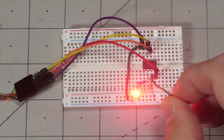
.jpg)
Image Credit: Screencap
Using an ATtiny for your project is typically an exercise in minimalism, and input with no external components is a powerful tool toward that end. One could implement a PCB with contact pads for each of the three analog pins (four if you include the reset pin/ADC 0). With careful geometric consideration, this functionality could potentially even be extended with multiple input options per pin. See Microchip’s capacitive sending guide for more technical background on this technology.
Alternatively, it should be possible to use external resistors for capacitive sensing with the ATtiny for “DIO touch” on every input pin. This would be similar to how my Pico Touch 2 capacitive sensing board, discussed here works, but on a smaller scale. While capacitance touch seems exotic, it’s actually a very accessible technology, and something that you may want to consider for your next ATtiny–or Arduino in general–project. On that note, I’d invite you to join me in the Developing With Arduino video series, where I expound on Arduino and Arduino-adjacent subjects!
Jeremy Cook is a freelance tech journalist and engineering consultant with over 10 years of factory automation experience. An avid maker and experimenter, you can follow him on Twitter, and see his electromechanical exploits on the Jeremy Cook YouTube Channel. He also hosts the upcoming Developing With Arduino online training series.