Part 2: Discovering an Efficient Active Balancing Solution for BMS Design
October 06, 2025
Blog
Simplicity and efficiency are not always a difficult trade-off; excellent and successful designs often combine both. This article introduces several traditional active balancing solutions for battery management systems (BMS) and discusses how to leverage the strengths of these popular approaches to develop a more practical solution that better achieves simplicity and efficiency in design. Finally, it explains why pack-to-pack balancing is just as important as cell-to-cell balancing.
Read part 1 here: https://embeddedcomputing.com/technology/analog-and-power/batteries-power-supplies/a-deeper-look-into-active-balancing-on-bms-part-1
Introduction
The simplicity and efficiency of an active balancing design are not merely a catchy slogan that is difficult to implement. In this article, we will examine and introduce several widely adopted active balancing solutions currently available on the market. By analyzing the respective advantages and disadvantages of each approach, we aim to integrate their strengths to develop a more practical solution that better achieves simplicity and efficiency. Finally, we will emphasize that while most existing active balancing designs have primarily focused on cell-to-cell balancing, pack-to-pack balancing is equally important and should not be overlooked.
Introduction to Existing Active Balancing Solutions in the Market
In Part 1 of this series, the importance of active balancing in battery management systems (BMS) was discussed. In fact, several active balancing solutions have been on the market for quite some time. Here, we will focus on three common active balancing solutions showcased in Figure 1. While it is impossible to cover all the available solutions in one article, the three presented here are highly representative of the field. They include active balancing solutions based on flyback, multi-inductor, and switched capacitors, which employ three widely used energy storage components in circuits: transformers, inductors, and capacitors. The working principles of these three active balancing solutions, as well as their respective advantages and disadvantages, are summarized in Table 1.
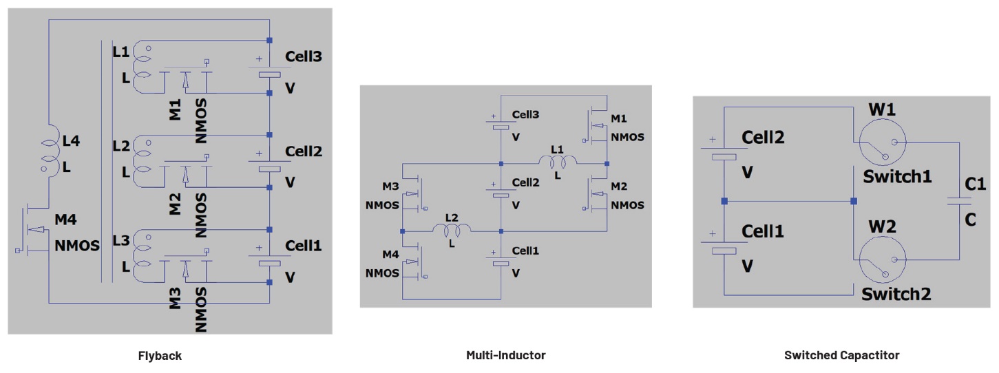
Figure 1. The three most representative architectures of active balancing solutions: flyback (left), multi-inductor (middle), and switched capacitor (right).
Table 1. Comparison of Working Principles and Advantages/Disadvantages of Three Active Balancing Solutions
|
|
Flyback |
Multi-Inductor |
Switched Capacitors |
|
Working Principle |
The flyback power architecture method enables unidirectional or bidirectional energy transfer between a module consisting of multiple cells and individual cells. This approach is primarily based on an isolated DC-to-DC topology for energy transfer. |
For every n battery cells, n-1 inductors and 2 × (n-1) switches are required to transfer energy. The switches operate using pulse width modulation (PWM) at relatively high frequencies, with the current flow and PWM duty cycle controlled according to energy transfer. |
For every n battery cells, n-1 capacitors and 4 × (n-1) switches are required for energy transfer. Through the switching on and off of the switches and the charging and discharging of the capacitors, energy can be transferred between adjacent cells. |
|
Advantage |
The balancing time is short, and the balancing efficiency is high; even nonadjacent cells can quickly achieve charge transfer. |
If charge transfer is only required between adjacent cells, this method is relatively efficient; the control mechanism is of moderate complexity. |
If charge transfer is only required between adjacent cells, this method is relatively efficient, and the control mechanism is simple. |
|
Disadvantage |
There is a high possibility that a custom transformer is required; the control mechanism is relatively complex. |
It is difficult to achieve charge transfer between nonadjacent cells; the charge transfer path between nonadjacent cells is long, and multiple transfers inevitably lead to more energy loss. |
It is difficult to achieve charge transfer between nonadjacent cells; the charge transfer path between nonadjacent cells is long, and multiple transfers inevitably lead to more energy loss. It is also difficult to scale the power level with capacitors without excessive I2R losses. |
Simplifying Active Balancing: A Smarter Design Approach
As previously discussed, traditional active balancing solutions tend to be either complex and expensive or simple and cost-effective but inefficient. The key question this article aims to explore is how to maintain excellent efficiency while ensuring the active balancing design remains sufficiently simple.
Reevaluating the Design Requirements of Active Balancing
Thanks to increasingly advanced battery manufacturing technologies and stringent quality control processes, the performance of individual cells—especially those of the same specification and sourced from the same manufacturer—is generally highly consistent. However, individual cells are typically not sold directly to end customers such as those in the electric vehicle (EV) or energy storage system (ESS) markets. Instead, professional battery pack manufacturers assemble multiple new cells of the same specification into medium to high voltage battery packs, which are then sold to end users like EV and ESS manufacturers.
From the above, it is easy to understand that for a newly assembled battery pack, the cells within are expected to have similar and consistent performance. However, it is important to note that before a new battery pack is used for the first time, the voltage and state of charge (SOC) of individual cells may not necessarily be consistent across the entire pack. This is because newly manufactured cells are not always assembled into packs immediately after production. Even after pack assembly, it may still take time before the product is shipped to the end user and put into actual use.
During extended periods of storage or transportation—whether for individual cells or for assembled battery packs—voltage and SOC imbalance among the cells can easily develop. This is not an uncommon issue. When a new or relatively new battery pack shows signs of imbalance after long-term storage or transport, this does not necessarily indicate a mismatch in cell performance. In fact, the cells may still have very similar characteristics. It is crucial to understand that similar performance does not inherently guarantee similar voltages or SOC levels, especially after prolonged storage or transit.
Therefore, it is generally recommended to perform active or passive balancing on battery packs or cells that have been stored or transported for extended periods before they are put into use.
Another situation worth highlighting is different from the storage and transportation scenario: After the pack has been in operation for a period of time and has undergone an increasing number of charge-discharge cycles, the performance gap between individual cells may widen compared to when the pack was initially assembled.
With the continuous growth in energy storage system capacities, individual cell capacities have now reached 320 Ah, 600 Ah, and even 1000 Ah. Among these, 320 Ah represents the previous mainstream, 600 Ah is becoming the current standard, and 1000 Ah is regarded as the future direction—some manufacturers have already achieved mass production capability for such high-capacity cells.
For large capacity battery packs that are either not equipped with active balancing or only utilize passive balancing, the initial minor imbalances between cells can gradually evolve into significant mismatches over time. This is due to the limited balancing capability and the cumulative effect of prolonged charge-discharge cycling. Eventually, such a cell mismatch may lead to significant capacity loss and safety risks (such as over-charging and over-discharging) during the actual operation of the battery pack.
Two Key Roles of Active Balancing
Since cell mismatch within a battery pack appears to be an unavoidable issue, active balancing can serve two main functions within a battery pack:
- Preventative function: In a battery pack where no significant mismatch exists, cells are in good condition, and performance differences are minimal. Here, active balancing has a relatively light workload. If we metaphorically compare active balancing to a doctor monitoring cell health, it only needs to conduct periodic checkups. This simple monitoring helps prevent or delay the amplification of performance discrepancies, minimizing the likelihood of cell mismatch and effectively extending the lifespan of the battery pack.
- Corrective function: In a battery pack where weak or unhealthy cells already exist, active balancing leverages its flexibility, large balancing currents, and fast balancing speed to redistribute charge between weak, unhealthy, and well-performing cells. This maximizes the lifespan of battery packs affected by cell mismatch, ensuring their safe and stable operation while reducing the risks of overcharging and over-discharging. More importantly, to minimize the impact of cell mismatch on the battery pack’s loss of capacity. At this stage, active balancing acts as a surgeon, diligently working to alleviate cell mismatch problems and prolong the battery pack’s lifespan.
Why and How to Simplify the Design?
Although the three popular active balancing solutions mentioned above have already been widely accepted and applied in the market, why continue to explore further simplification of active balancing designs? The reason is that while these three solutions—and even other approaches not covered here—are all well-established and effective, they still hold significant potential for improvement.
The main objective of this article is to analyze past solutions, leverage the strengths of these popular approaches, and develop a more practical solution that better achieves simplicity and efficiency in design.
For example, the flyback isolated active balancing architecture is particularly known for its high efficiency, especially when balancing is required between nonadjacent cells—where it clearly outperforms other methods. On the other hand, multi-inductor and switched capacitor-based active balancing methods excel in efficiency when balancing adjacent cells, offering simpler control logic, stable operation, and robust performance.
In summary, if a simplified solution is expected to deliver high balancing efficiency, the flyback-based balancing circuit architecture should be prioritized. However, flyback-based balancing circuits typically require transformers, and using a large number of transformers can lead to increased cost, larger system size, and more complex control logic. Therefore, when aiming for a simplified design, it is crucial to maintain high efficiency while minimizing the number of transformers used. A straightforward idea is to allow all cells within the battery pack to share a single flyback circuit and transformer.
But simplifying the hardware and reducing the number of transformers alone is not sufficient. Another critical aspect is the simplification of control logic and operational strategy. Active balancing is a system-level solution; designers must not only consider which ICs and components to use for implementing the energy transfer in hardware but also pay close attention to the balancing strategy—that is, the design of the active balancing algorithm, which falls under system software design.
In general, the design of the battery balancing algorithm varies depending on the hardware architecture it supports. Therefore, achieving a simplified balancing hardware design while also reducing the complexity of the algorithm design remains a key challenge that must be addressed.
A Simplified Active Balancing Design
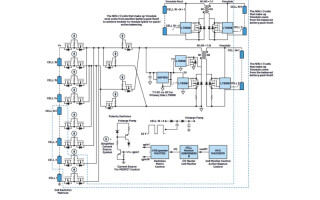
Building upon the concepts discussed above, this article proposes a simple yet efficient active balancing solution, as illustrated in Figure 2. The design features a 16-cell battery pack utilizing two separate flyback circuits with two transformers—one designated for cell-to-cell balancing and the other for pack-to-pack balancing.
For the cell-to-cell balancing portion, all 16 cells share a single flyback-based active balancing power circuit. A switch matrix is employed to selectively connect the balancing circuit to different cells, enabling them to time-share the same hardware resources. This design is both straightforward and elegant, avoiding unnecessary complexity while maintaining high efficiency and robust performance. As a result, the approach presents a compelling advantage in active balancing system design.
Moreover, the solution supports bidirectional balancing not only between individual cells but also across multiple packs, significantly enhancing the effectiveness of cross-pack balancing. Unlike conventional solutions that often rely on independent external power sources—such as separate 12 V or 24 V batteries—to support either cell-to-cell or even pack-to-pack balancing, this design operates entirely using energy from within the battery pack itself. This not only improves overall system efficiency but also reduces both hardware and software design complexity.
Regarding the simplified balancing algorithm design, more detailed discussions will be provided in Part 3 of this article series. However, two key principles of the algorithm are:
- Since true bidirectional cell-to-cell balancing is not feasible within the pack without excessive complexity, the algorithm relies on an intermediate charge buffer to facilitate indirect balancing. Specifically, n adjacent cells within the pack are designated as the buffer. Balancing is then achieved through a two-step process: a cell-to-buffer discharge, followed by a buffer-to-cell recharge, effectively emulating bidirectional charge transfer between individual cells.
- During the cell-to-buffer discharge, the energy from the source cell is evenly distributed among the n buffer cells. Conversely, during the buffer-to-cell charge, the required energy for the destination cell is evenly drawn from the n buffer cells.
By simplifying the hardware architecture while retaining high-performance balancing capabilities, this approach offers an optimal trade-off among cost, efficiency, and real-world applicability—making it a highly practical and scalable solution for advanced BMS deployments.
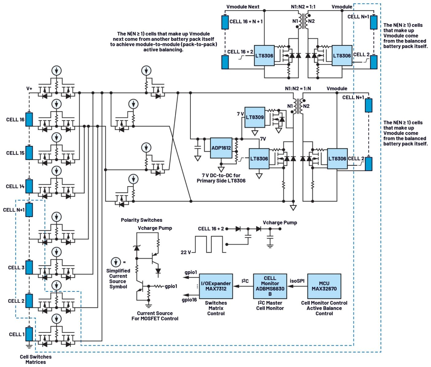
Figure 2. The diagram of the proposed simplified active balancing solution using the LT8306, LT8309, ADP1612, MAX7312, MAX32670, and ADBMS6830B.
Why Pack-to-Pack Balancing Is Equally Important
Before continuing with the discussion of the proposed solution, let’s first explore why pack-to-pack balancing is also crucial.
In a system consisting of a BMS and a battery pack, multiple circuit modules—including the cell monitor, isolated communication, temperature sensor, active balancing, and passive balancing, etc.—consume power as the BMS operates. However, achieving identical power consumption levels across different BMS circuits is challenging. Even if we assume that two BMS circuits have nearly identical power consumption, the situation becomes more complex if the two BMS circuits monitor battery packs with different numbers of cells (which is not uncommon).
In such cases, the battery pack with fewer cells requires a larger IMONITOR supply current for its cell monitor. Over time, as the difference in supply current accumulates, the imbalance between the two battery packs becomes more severe. Without proper balancing adjustments, this disparity leads to significant capacity mismatch between packs. This is why pack-to-pack balancing is equally important. See Figure 3.
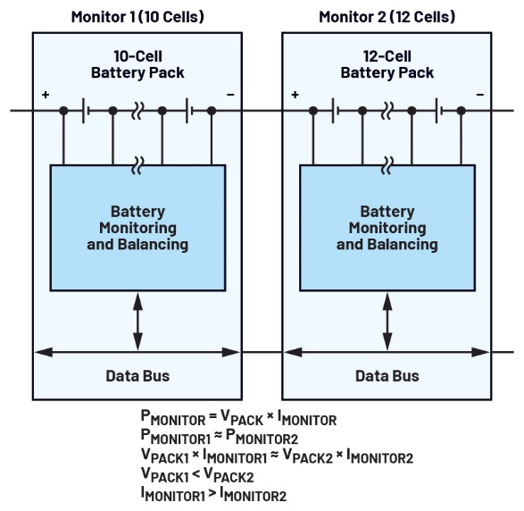
Figure 3. Illustration of mismatch conditions between battery packs.
Conclusion
This article introduces several popular active balancing architectures commonly found on the market and, by leveraging the strengths of each, proposes a more practical solution that better achieves simplicity and efficiency in design.
Nevertheless, it is important to acknowledge that, despite the emphasis on the simplicity and efficiency of the proposed balancing solution, no single design can effortlessly address all cell mismatch scenarios in real-world applications. This is especially true as individual cell capacities continue to increase—from 320 Ah to 600 Ah and even 1000 Ah. Under such conditions, any balancing strategy must be carefully evaluated and validated before being deployed in a battery pack.
Analog Devices offers solutions covering nearly all mainstream active balancing architectures, including those discussed in this article. Each architecture comes with its own advantages, limitations, and ideal application scenarios—giving system designers the flexibility to select the most appropriate solution based on their specific needs.
In the next article, we will engage in a more practical discussion, guiding readers through the design and implementation of a simple yet effective active balancing prototype.
Frank Zhang is an application engineer working in Central Applications China at Analog Devices. His areas of expertise are battery management systems (BMS), precision signal chains, and embedded software development. He received his M.S.E.E. degree from Fuzhou University in 2022 and joined ADI in the same year.

Frank Zhang is an applications engineer working in Central Applications China at Analog Devices. His areas of expertise are battery management systems (BMS), precision signal chains, and embedded software development. He received his M.S.E.E. degree from Fuzhou University in 2022 and joined ADI in the same year.