A Deeper Look into Active Balancing on BMS - Part 1
September 02, 2025
Blog
Simplicity and efficiency—even if not the shared pursuit of all designers—are the goals for most. Following the principle that simplicity wins, this article delves into and explores the design prototype of a simple yet efficient active balancing system for battery management systems (BMS).
Fair, this perspective is not entirely due to an evaluator’s prejudices—it is often based on an objective and impartial assessment of the numerous active balancing solutions currently available on the market.
This article series is divided into three parts:
- Part 1 explores the impact of cell capacity mismatch and impedance mismatch on battery management systems (BMS) battery packs.
- Part 2 introduces several traditional active balancing solutions available in the market and analyzes why past designs have failed to achieve simplicity and efficiency. It also discusses why pack-to-pack balancing is just as important as cell-to-cell balancing.
- Part 3 delves into the evaluation of a simple and efficient active balancing prototype, including circuit design, algorithms, GUI, and balancing performance.
As the discussion progresses from fundamental concepts to in-depth analysis, readers—whether professionals and engineers in the field of BMS and active balancing, or simply curious individuals drawn in by the title—will find valuable insights and takeaways in this article.
Impact of Cell Mismatch on BMS Battery Packs
In a BMS, multiple individual cells are typically connected in series to form a high-voltage battery pack. This high-voltage battery pack is the supply for various systems, including electric vehicles, high-voltage energy storage systems, and uninterruptible power supplies. In these series-connected cells, the ideal operating condition is that all individual cells have consistent parameters such as cell voltage, internal impedance, state of charge (SoC), state of health (SoH), and operating temperature.
In reality, when a batch of brand-new cells is first produced by the manufacturer, their performance and specifications are generally consistent. However, after being put into actual use, as the cells age, inevitable differences in performance arise due to factors such as load, environmental temperature, and humidity, and the number of charge cycles.
When the performance differences between cells are small, they typically do not threaten the normal operation of the battery pack and do not require special attention. But once the performance differences between cells become significant enough to threaten the proper functioning of the battery pack, it is crucial to address this issue. These significant performance differences between cells will be referred to as cell mismatch in the following sections.
Cell Capacity Mismatch
As shown in Figure 1, if a few cells in a battery pack have significantly lower capacity than the others, they are referred to as weak cells. These weak cells pose issues during both charging and discharging. During charging, a weak cell will reach full voltage more quickly and become fully charged ahead of the others. However, because the cells are connected in series as part of a larger battery pack, the charging current does not automatically stop once the weak cell is full. As a result, the entire battery pack’s charging process must be halted as soon as the weak cell reaches full charge to avoid the risk of overcharging, which could endanger both the weak cell and the entire battery pack.
Similarly, during discharging, the weak cell’s voltage will drop faster, and it will reach its fully discharged state sooner than the rest. Again, the discharge process of the entire battery pack must stop immediately once the weak cell is fully discharged, or it risks being over-discharged, which also poses safety concerns. Observant readers may quickly realize that in a battery pack containing weak cells, the overall capacity utilization is significantly reduced. Without cell balancing, healthy cells are unable to be fully charged or fully discharged during each cycle. Over time, as the cell undergoes repeated charge and discharge cycles, the weak cell—being subjected to more cycles—tends to experience faster capacity degradation, which worsens the mismatch with other healthy cells.
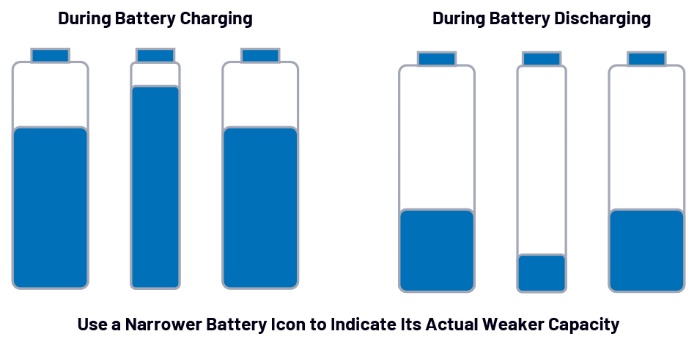
Figure 1. Impact of capacity-mismatched cells during battery pack charging and discharging.
Cell Impedance Mismatch
Apart from cell capacity, another important parameter of great concern is cell impedance. Similar to capacity mismatch, impedance mismatch occurs when a cell within a pack exhibits significantly different impedance compared to others. Some engineers use the electrochemical impedance spectroscopy (EIS) method to measure each cell’s impedance and assess its health status. A healthy or relatively new cell typically has lower impedance, whereas an aging or unhealthy cell tends to have higher impedance. The following illustration provides a more intuitive understanding of how impedance mismatch affects battery pack performance.
If a particular cell within the pack has significantly higher impedance than others, it is referred to as an unhealthy cell for ease of discussion. Figure 2 visually demonstrates this phenomenon by representing the cell as a simplified circuit model with a capacitor and a resistor in series during charging and discharging. It is important to note that this abstraction is a necessary simplification for discussion purposes in this article; while suitable for illustrating impedance mismatch effects, it does not represent the actual physical and electrical characteristics of a real cell.
During charging, an unhealthy cell with higher internal impedance experiences a greater voltage drop under a given charging current. In this case, if all cells exhibit the same voltage value, the unhealthy cell will actually store less energy. As shown in the figure, the unhealthy cell has a smaller Vcell_actual value during charging. Additionally, due to the higher power loss caused by its impedance, the unhealthy cell typically experiences a higher charging temperature.
During discharging, a higher impedance results in a greater voltage drop and higher power dissipation under a given discharge current. Consequently, the unhealthy cell experiences a more rapid decline in voltage and capacity and generally operates at a higher discharge temperature. Over time, with repeated charge-discharge cycles, the higher temperature and aging effects further accelerate impedance increase in the unhealthy cell, exacerbating the impedance mismatch issue within the battery pack.
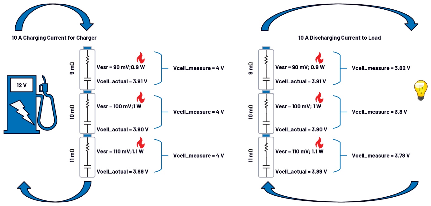
Figure 2. Impact of impedance-mismatched cells during battery pack charging and discharging.
By analyzing both capacity mismatch and impedance mismatch, careful readers may observe that although these two mismatches represent different aspects of cell imbalance, their ultimate effects are quite similar. Whether it is a weak cell with lower capacity or an unhealthy cell with higher impedance, both issues primarily impact the usable capacity and operating voltage of the battery pack. In a battery pack with weak or unhealthy cells, the overall capacity utilization and safe operating time are significantly reduced. Moreover, these mismatched cells pose a continuous threat to the safety and normal operation of the well-performing cells within the pack.
The Critical Importance of Passive/Active Balancing in BMS
With the previous discussion on cell mismatch issues, understanding the application of passive and active balancing in BMS becomes much easier.
Passive balancing is a dissipative method that typically operates during the charging cycle. Since weak cells have lower capacity, their voltage rises faster under the same charging current. When they reach or approach full charge first, the excess energy must be immediately dissipated. Although this energy dissipation leads to heat generation and thermal management challenges, it extends the charging time for healthy cells, ultimately improving the overall run time of the battery pack. Passive balancing is widely adopted in BMS, with most cell monitoring ICs already integrating this functionality.
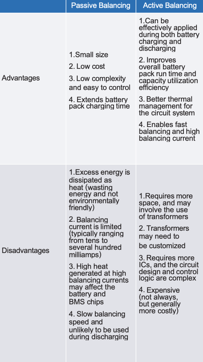
Active balancing, on the other hand, transfers energy between cells using transformers, capacitors, and inductors. This method works during both charging and discharging cycles, redistributing charge efficiently. While both passive and active balancing have their advantages and disadvantages (summarized in Table 1), the choice of balancing method in practical BMS design is not simply based on a direct comparison of their pros and cons. Instead, it depends on the capacity and scale of the battery system.
Generally, the balancing current is set to about 1% to 5% of the cell capacity. For example, in a 4 Ah lithium cell, if the balancing charge is 5% of its capacity, then 200 mAh needs to be equalized. This scenario is well-suited for passive balancing, where a BMS designer can implement a 200 mA passive balancing circuit to dissipate the charge in about an hour or a 100 mA circuit to do so in two hours. Ultimately, the designer can tailor the passive balancing strategy based on the passive balancing current capability of the selected cell monitor IC and the cell capacity.
In contrast, consider a 300 Ah high-capacity energy storage cell where the balancing charge at 5% reaches 15 Ah. Even with a 300 mA passive balancing current—which is already quite high—it would take over 50 hours to complete balancing. In reality, this time would be even longer, as continuous passive balancing on a single cell channel for extended periods could overheat and may damage the BMS chip. Therefore, active balancing is essential for high-capacity cells.
For instance, if an active balancing circuit can handle 15 A of charge transfer, the 15 Ah imbalance can be corrected in about an hour. With a 7.5 A capacity, it would take about two hours, and so on. Unlike passive balancing, active balancing does not waste energy but rather redistributes it to other cells or packs, improving overall energy efficiency while easing the thermal management burden of the BMS.
Table 1. Advantages and Disadvantages of Passive and Active Battery Balancing
Conclusion
In this article, we introduced the impact of cell capacity mismatch and impedance mismatch on the normal operation of a battery pack. We also provided an overview of both passive balancing and active balancing methods in BMS, laying the groundwork for further discussion in subsequent articles.
Frank Zhang is an applications engineer working in Central Applications China at Analog Devices. His areas of expertise are battery management systems (BMS), precision signal chains, and embedded software development. He received his M.S.E.E. degree from Fuzhou University in 2022 and joined ADI in the same year.

Frank Zhang is an applications engineer working in Central Applications China at Analog Devices. His areas of expertise are battery management systems (BMS), precision signal chains, and embedded software development. He received his M.S.E.E. degree from Fuzhou University in 2022 and joined ADI in the same year.