Nothing is Impossible... During Assembly Testing!
July 22, 2024
Blog
The latest requirements are constantly challenging test engineers with new tasks
The increased use of highly integrated electronic circuits is presenting new challenges for test engineers in manufacturing. Miniaturization often limits the number of applicable test methodologies. Test systems proven over several decades, such as in-circuit test (ICT) or flying-probe test, are reaching their limits because it is no longer possible to contact all the points needed for good coverage.
Higher interface speeds also challenge developers of functional tests. Still, to keep the cost of test and the cost of repair low, faults must be detected as early as possible in the product’s life cycle, ideally in the early stages of the manufacturing process. Most commonly, defects on printed circuit board assemblies are introduced during manufacturing, typically due to soldering problems and/or incorrect components placement.
Defective components make up a small proportion of failures, as the component manufacturers have already carried out intensive tests on their components. However, for the high signal speeds common with today’s designs, fault-free solder connections are crucial for a reliable and robust function of the end product. Considering the latest volatile random-access memory (RAM) components, we can see that established test methodologies such as JTAG/Boundary Scan (per IEEE 1149.1) can still deal with these challenges quite well.
Electrical test in the manufacturing process - what can Boundary Scan do?
Boundary-scan tests are “structural” and somewhat “static” electrical tests that are carried out via the 4-wire JTAG interface. In this context, “structural” means that the focus is on the verification of the connections of the component pins. “Static” means that the test is performed much slower than the nominal speed of the component or circuit.
All boundary scan-capable components are connected in a serial chain for these tests, which greatly simplifies signal routing on the printed circuit board. With the help of boundary-scan technology, not only connectivity tests between IEEE 1149.x conformant components are carried out.
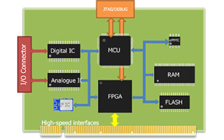
Non-boundary scan-capable components can be functionally controlled, too, as illustrated in Figure 1. This test methodology is very well adapted to detecting and localizing structural defects like solder bridges between two pins. This is a major advantage compared to most functional tests. With the bidirectional mode of operation of boundary-scan pins, a logic level can be driven while at the same time measuring the level established on the net, supporting the detection of so-called "stuck-at" faults (i.e. solder bridges to operating voltage or ground). This is often not possible during functional tests.
.png)
Figure 1: Block diagram of a typical assembly under test (source: GÖPEL electronic)
Testing new and complex RAM circuitry for manufacturing defects
In contrast to functional tests, the boundary scan-based RAM test only verifies the connections to the RAM and not the entire RAM storage space. Due to the serial nature of the JTAG chain, the basic mechanism for boundary-scan access, the achievable data throughput is inversely proportional to the length of the boundary-scan register so that comprehensive RAM cell tests would take far too long.
In manufacturing and assembly tests, proper solder joint connection is of primary interest. Boundary-scan based RAM tests follow the same principles as functional RAM test, in the sense that basic RAM initialization is carried out first and then certain optimized test patterns for the detection of failures are written to the RAM and then read back (see Figure 2). This applies to simple SRAM as well as to the latest LPDDR5 devices.
The complexity and number of the connected RAM devices themselves are irrelevant, i.e. the RAM models are designed in such a way that the necessary tests can be generated automatically with the help of the boundary-scan software, without the user needing to have any specific knowledge of the respective RAM devices.
With its innovative products, GÖPEL electronic has always been a pioneer when it comes to testing such components. The testing of SRAM, DRAM, DDR1, DDR2 and DDR3 RAM components is an established part of the embedded JTAG solutions platform software SYSTEM CASCONTM, being employed every day in countless customer assembly test applications.
In addition, GÖPEL electronic is one of the first providers to support the boundary-scan test of the latest memory chips such as DDR4, LPDDR4 and LPDDR5. For this purpose, the company supplies an ever growing component library with SYSTEM CASCONTM, which includes ready-made and tested descriptions for functional access so that the RAM test can be generated very quickly and automatically. The user only assigns the model from the library to the corresponding component on the unit under test (UUT).
The specialized test patterns used in boundary-scan based RAM connection tests enable the targeted detection of short-circuited or unsoldered pins. The ever-increasing speeds of RAM components suggest that it is becoming increasingly difficult to test such components using static test procedures. However, many years of experience in assembly test demonstrate that connectivity for these components can be tested successfully with a small set of quasi-static test patterns.
Thanks to features such as self-refresh or internal clock generation built into RAM devices, such components can be written to and read from without any problems, even at very low access speeds, with the test pattern written into the memory being retained long enough for the test sequence to complete.

Figure 2: Signal waveform for an LPDDR5 RAM test in the SYSTEM CASCONTM debugger (source: GÖPEL electronic)
Certain RAM types, such as DDR4 or DDR5, provide a special connectivity test feature, which is typically activated with a TEN pin on the RAM device. When this test mode is active, combinatorial logic is placed between the component’s input and output ports, bypassing the normal memory array, avoiding the need for complex initialization, write, and read sequences. Typically, the data lines are used as outputs and the address and control signals as inputs for that combinatorial logic. A practical example of such a logic connection in a DDR4 RAM looks like this:
DQ2 = A2 XOR A5 XOR A13 |
If this connectivity test mode is not available (e.g. with LPDDR4 or LPDDR5), only boundary scan-based RAM tests can be used. The latter write certain test patterns to the memory array and read them back. This allows shorts and opens, e.g. caused by solder bridges or unsoldered pins, respectively, to be detected precisely at the net level. This test therefore not only detects faults, but also identifies the fault location, including the RAM control lines. With conventional function tests, these cannot always be located precisely in the event of a fault, functional access to the RAM either works or not.
The embedded JTAG solutions (EJS) platform software SYSTEM CASCONTM from GÖPEL electronic also offers further optimizations in the RAM test generator to minimize the test time. For example, a so-called Go/No-Go test with reduced test patterns can be included automatically. At the beginning of the test, basic test patterns are executed that facilitate fault detection. Only when a fault is detected more specialized and extensive test patterns are applied for the exact diagnosis at net and pin level. This saves valuable test time, which is an important requirement for in-line production systems in particular, as the test procedure must not impact the manufacturing cycle time negatively.
Simple and reliable product tests save time and costs
The discussed solutions for simple structural boundary-scan tests show that extensive assembly tests and, above all, precise defect localization, can be accomplished even without functional tests. SYSTEM CASCONTM is a valuable tool for design and test engineers, as many tests can be generated very quickly and easily in a fully automated manner, saving test development time and ultimately troubleshooting cost (see Figure 3).

Figure 3: Overview of cost factors for failures found (source: EP-TEQ)
The availability of new library models for the latest LPDDR5 RAM devices is another valuable part in GÖPEL electronics’ portfolio, which in its entirety, helps users create agile test solutions for use throughout the entire product life cycle, from design development, through manufacturing test, to repair and maintenance of assemblies.