Tasmota Breathes IoT Life Into Decades-Old Garage Door Opener
December 29, 2023
Blog

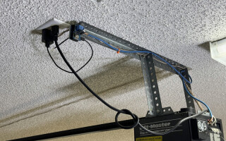
My house has a perfectly serviceable “Lift-Master” garage door opener, installed decades before I moved in. Before, in fact, “IoT” was even a term (or practically even “I”) as its manufacturing date reads as 02/94. Nonetheless, this device’s hardwire interface–a set of dry contacts–is refreshingly easy to modernize with the addition of an IoT-controlled relay and Tasmota.
Hardware Setup
Image Credit: Jeremy Cook
When garage door contacts 1 and 2 are manually shorted, the garage is activated. This allows for manual operation via a doorbell-style switch, which can be duplicated via a relay in parallel. To automate this operation, I used strands from a length of Ethernet cable, wired into normally open (NO) relay contacts controlled by an ESP8266 dev board. Components used (or versions thereof) are listed below:
- Wemos/LOLIN D1 Mini ESP8266 dev board
- D1 relay shield
- D1 dual base for easy shield mounting
- D1 dual base zip-tie mounting plate
- Ethernet cable, ferrules, (possibly optional) capacitor between 5V and GND
To set things up hardware-wise, assemble the Wemos and relay setup as shown. Connect one opener contact to the NO relay contact. Connect the other opener contact to the common relay contact.
.jpg)
Image Credit: Jeremy Cook
Programming
Getting this sort of ESP8266 device is quite easy, using the fantastic Tasmota firmware, but there are a few tricks that you’re likely to overlook the first time (if you’re not following along with this guide). To install the firmware:
- Connect the D1 Mini via USB
- Download Tasmota binary file from this page. I used Tasmota-4M.bin under the Initial Firmware column.
- Navigate to Tasmota web installer page on a compatible browser (e.g. Chrome), follow on-screen instructions to upload the .bin firmware file, connect, flash, and set up your WiFi connection.
With Tasmota now functional, you can click on “visit device” to set things up as needed. You can also find it on your network via an IP scanner program, such as Angry IP Scanner.
To configure your device, navigate to Configuration - Configure Module. Set the Module type to Generic (18) and save this setting. Set D1 GPIO5 to Relay, 1 and save again.
.jpg)
Image Credit: Jeremy Cook
This allows you to toggle the relay on and off manually, but what we really want it to do is close the relay momentarily, then automatically open it a short time later. To set this up:
- Navigate to the Main Menu – Consoles – Console
- Enter switchmode1 13 to set your switch 1 to switch on for a set period
- Enter pulsetime1 1 to set the switchon period in .1 second increments (here .1 second)
Navigate back to the main menu and toggle the button to see it pulse on for .1 second, then turn off. Information on SwitchMode, PulseTime, and more (much more) is available in the Tasmota documentation. Also, you can use templates to help set up your system, which is very helpful for more standard installations (e.g. smart bulbs).
Tasmota Interface Notes: Organize and Access Locally
Image Credit: Jeremy Cook
To change the hostname that shows up when you use an IP scanner–extremely useful as your home automation fleet expands–go to Configuration – Configure WiFi, type in the new name under Hostname, and save. IP scanning will now reveal the easy-to-remember name of your choosing, and you can access it in a browser by simply inputting hostname/ as the address.
Once programmed with Tasmota and accessible via a local web interface, you can save the page as an icon on your phone (iOS, Android). You can also put it in a folder (place one icon over another to create a folder) with other home automation “things,” allowing for easy access with minimal hassle.
Finally, to rename the web interface buttons: from the console, type webbutton[x] text goes here, where [x] is the number of the component/GPIO in question. In this case the toggle button would be webbutton1.
Programming and Development Addendum
The preceding section is a good and rather straightforward way to get your mid-90s garage door opener working via a smartphone or other smart device, and is how I programmed it as of this December (2023). However, I actually “finished” this project in 2020 using Arduino C code. This method took significantly more work, resulted in a much less robust web interface, and stopped working at some point.
Perhaps the more general lesson here is that as you go down a project path, it can be a good idea to take a step back and consider what else is out there. Perhaps someone has already done the hard work for you–and done it better than you will. I’d encourage you to see if there is an even better solution available at the time of your reading.
On that note, use these instructions at your own risk, and note that your opener may work differently than mine. It would be a good idea to consult your opener’s manual before trying any such operation!
Jeremy Cook is a freelance tech journalist and engineering consultant with over 10 years of factory automation experience. An avid maker and experimenter, you can follow him on Twitter, and see his electromechanical exploits on the Jeremy Cook YouTube Channel. He also hosts the upcoming Developing with Arduino online training series, where you can learn about using devices made by the Raspberry Pi Foundation.

.jpg)
.jpg)


