Use Serial and I2C With the Arduino Opta PLC
September 26, 2024
Blog

The Arduino Opta Lite, as introduced here, as well as in my Developing With Arduino online training series, is a neat device that could be billed as a PLC, or even as a programmable relay. While it has a USB-C port for programming, as well as an RJ45 Ethernet port, what seems to be missing versus a typical Arduino dev board is a standard serial interface for troubleshooting and communication, as well as an I2C interface.
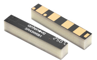
In reality, both serial and I2C are available, hidden behind the mysterious pop-off AUX tab. Remove the AUX tab and you’ll find a card-edge connection, normally meant for OPTA expansion modules, which includes pads for 5V, 3.3V, GND, TX, RX, SDA, and SCL. You could, in theory, solder onto these pads, but I instead designed a breakout board to help with this connection task.
This OPTA AUX serial/I2C breakout board is available for purchase as part of a kit that includes the requisite card edge connector. A version of the gerber files is found on GitHub, and the card-edge connector is a KYOCERA AVX 009159010061916 device. While this kit wouldn’t be appropriate for heavy industrial use, it should be a helpful tool for experimentation and development. If you need more robustness, perhaps a bit of hot glue, or even epoxy, between the connector and breakout could help keep it in place.
Arduino OPTA AUX Serial Communication

Image Credit: Jeremy Cook
To test out serial communication, I loaded code on the Opta which outputs characters based on the user button state to its standard USB serial port, as well as to the AUX Serial1 port. When connected to another Arduino board’s RX/TX pins (reversing RX and TX between the two), the two devices can communicate back and forth.
This extra serial port meant I could use the OPTA’s USB port for programming and monitoring, while communicating with the Uno via the Serial1 port. Code for the OPTA TX test is found here, which sends the state of the button +1 to trigger an LED on the receiving Arduino Uno, running this code.
That Uno code can pass the signal along via a software serial port to another connected board, and on and on, in theory repeating to infinity. I used that same OPTA code modified as shown below to detect serial input from the Uno, and the DigitalReadSerial example built into the Arduino IDE to send signals (also lightly modified).

Image Credit: Jeremy Cook
Arduino OPTA I2C Communication Setup
With the proper lines connected to a generic SSD1306 124x64 OLED display, communication was even more straightforward than serial. In this case, I loaded the ssd1306_128x64_i2c.ino example from Adafruit’s OLED library, changing the screen address from 0x3D to 0x3C to match my display. Adafruit’s example animations soon showed on the screen via the OPTA without further tinkering. I only tested I2C output from the OPTA to a device, but per this demo, I2C appears to work quite well in either direction.
Musical PLC Inspiration
After making this Opta auto-drums setup for my Cooked Audio YouTube Channel, per a comment there, I wondered if it would be possible to use MIDI to control the Opta part of a more involved musical instrument.
A software serial interface via the input pins seemed like it might be possible (MIDI is a serial specification), but after a bit more poking around it seems this would likely take a more advanced level of firmware hacking than I’m prepared to perform.
So after some initial frustration, an excellent connector suggestion, and an hour or so on KiCad, I have a connector and experimental serial interface methodology that works quite well. I2C communication was not my initial goal, but this capability is a very nice bonus. Note that while 5V is available, it seems these inputs use 3.3V. I would stick to that voltage level for serial/I2C interfacing unless you have further knowledge on the subject.