Understanding UEFI Firmware Update and Its Vital Role in Keeping Computing Systems Secure
June 10, 2022
Story
In this article, we will cover the methods in which compute-based platforms can be updated in the field in a secure, manageable, and observable fashion.
Throughout the article, we will also cover what underlying components exist to make all of this work, specifically in the context of a UEFI-based firmware implementation Beyond BIOS.
Let’s start with “platform firmware” and in this case, platform firmware is defined by the embedded logic that helps to initialize platform hardware and launches a boot target. This firmware usually resides on the computer’s motherboard or even on chips residing on plug-in devices such as storage controllers and network devices.
Ultimately, the main point of platform boot firmware is to launch a target piece of software, typically an operating system.
Historically, the boot firmware did not have a standardized set of Application Programing Interfaces (APIs) that were interoperable across the platform, third-party hardware, and operating system domains. Each of those components had its own programmatic silos with little standard interaction.
However, in 2005 the UEFI (Unified Extensible Firmware Interface) Forum was established. One of its primary goals was to provide an industry standard for how components within the machine may communicate with each other.
Briefly, the UEFI Forum covers three main specifications:
-
- UEFI Specification
- The set of APIs between the platform and third-party content such as an operating system or plug-in devices.
- Platform Initialization (PI) Specification
- Defines how the underlying platform firmware can be built.
- Advanced Configuration and Power Interface (ACPI) Specification
- Defines abstractions for non-discoverable info and runtime interactions from the platform to the operating system.
- UEFI Specification
As noted above, the firmware performs many roles. The implementation of the firmware is based upon industry standards, such as the UEFI PI specification. The PI phases include Pre-EFI Initialization (PEI) and Driver eXecution Environment (DXE). Typically, a platform may have 50 PEI modules and 180 DXE modules. The source tree to build these elements can comprise several hundred thousand lines of C code and as products are released, various branches are curated as shown below in Figure 1.

Figure 1 Evolution of a firmware source tree product
These modules and drivers all execute within ring 0 and typically don’t have intercomponent separation, which is common in applications within an operating system. As such, a flaw in any component can lead to a potential compromise of the platform. Many of these components consume attacker-controlled input, such as data structures on disk, policy objects like UEFI variables set by the operating system and input from unprotected buses. This large amount of executable code has many attack surfaces and as new technologies are introduced, more surfaces are created. Support for the various standards that UEFI firmware implementations must support increases in complexity. The evolution of such standards can be seen in figure 2 below.

Figure 2 Evolution of specifications and standards supported by firmware
Regarding the classes of attacks, there are many that have been observed in the market. These include privilege escalations into the early PI or later DXE flows, errant option ROM’s (intended to initialize special devices), or even attack hardware. A sample of the class of attacks against firmware can be seen in Figure 3 below.

Figure 3 Taxonomy of firmware attacks
There are reporting mechanisms through the UEFI Forum and via the open source community to support responsible disclosure of these security issues. The challenge, though, is the diffuse supply chain. For example, the use of the EDKII code on tianocore.org goes through many hands, such as open source to silicon vendor, silicon vendor to Original Equipment Manufacturer (OEM), and OEM to Original Device Manufacturer (ODM). How does a flaw in TianoCore for example, end up getting updated in an end-user flash ROM on their system for a device produced by the ODM? The complexity of today’s supply chain and patching can be demonstrated in figure 4 below.

Figure 4 Supply chain of UEFI firmware
What is the role of host firmware?
The boot firmware initializes in phases, including PEI and DXE, as illustrated below in Figure 5.

Figure 5 Boot flow of UEFI PI firmware
In the (DXE) Driver Execution Environment we enumerate the devices on the platform and then execute logic to initialize those devices. Sometimes those devices may have built-in support within the firmware if they are well-known and comply with certain standards, while others may have initialization code that the device carries and it, in turn, gets launched by the firmware.
In the latter case, the device’s initialization code will often expose a Firmware Management Protocol (FMP) interface that can be used for in-field updates if needed.
The last phase of the firmware initialization is when the operating system loader interacts with the firmware through UEFI APIs and facilitates its own initialization. It can also execute firmware updates through a variety of means like a capsule-based update.
As mentioned, a firmware change can traverse a tortuous path through the supply chain of silicon vendors, firmware vendors, OEMs and ODMs to appear in an end-user system. Historically many of these parties had custom updating tools that had to be installed into the various operating systems and unique locations to discover and download updates. This obscurantist space, namely how to update your device, often led many end users to not service their device and update their firmware in a timely manner.
Enter the UEFI Capsule. The UEFI capsule entails various elements, including a binary encapsulation of the update itself into something called a UEFI Capsule. The UEFI Capsule has a well-defined header named by a Globally Unique Identifier (GUID). The producer of the system firmware wraps their update payload—be it code, data, or even an update driver—into this format. The provenance of the update is then guaranteed by applying a cryptographic signature across the capsule using keying material owned by the capsule producer. A pictorial representation of the capsule can be found in figure 6.

Figure 6 Layout of a capsule
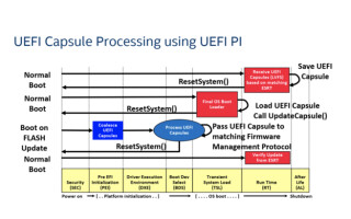
Once the capsule is in hand, the OS can ascertain if the platform supports this capsule type by referencing the EFI System Resource Table (ESRT), which is a series of GUIDs designating the version and potentially updatable elements in the platform. If the capsule GUID in hand has a match to a ESRT entry, the operating system can stage or a pre-OS UEFI application will issue an UpdateCapsule() UEFI runtime call with the aforementioned capsule binary as an argument. Linux and Windows typically stage the update by copying the capsule to a pre-OS accessible location, such as the EFI System Partition (ESP), and reboot. Upon restart, the UEFI OS loader can issue the UpdateCapsule() call and the device will restart. During the restart the UEFI PI code will ascertain the capsule location, possibly coalesce, cryptographically verify, and if authentic, update the flash with the update. The overall flow is shown in the figure 7 below.

Figure 7 Capsule update boot flow
Once the update has occurred, there may be some concern with system stability. As such, there are capabilities in the UEFI ACPI specification, such as the Platform Health Assessment Table (PHAT), that can be queries to see if there is any unexpected change in system state. An update can also impact system integrity as noted by changes in the Platform Configuration Registers (PCRs). As such, prior to the update the operating system may need to unseal secrets, issue the update and then re-seal against the latest PCRs.
In order to facilitate the ecosystem creating capsules, there is the TianoCore /EDK2 resource provides a template for creating an update driver based up on the UEFI Firmware Management Protocol, creating an ESRT entry, signing, etc. There is also support in the ecosystem for managing capsule updates in Linux with the Linux Vendor Firmware Service (LVFS) and Windows Update (WU). Given that a chain is only as strong as its weakest link, some best practices on building high assurance firmware can be found in Building Secure Firmware.
In summary, this article has discussed the means by which to perform firmware updates in a secure, manageable, and observable fashion. These properties are enabled via the infrastructure in UEFI-based firmware, including capsules, PHAT, and FMP protocols based upon cryptography.
Michael Rothman is an engineer at Intel Corporation. He has worked at Intel for over twenty years and participates extensively in firmware-related industry standards.
Vincent Zimmer is a senior principal engineer at Intel Corporation. Vincent has worked at Intel for over 25 years and chairs the UEFI Security Sub-team. Vincent has many publications, including https://www.amazon.com/Vincent-Zimmer/e/B002I6IW4A/.