Quick Guide for Implementing Automotive Audio Bus (A2B) Based Solutions on STM32 Platform
March 11, 2022
Blog
This article covers the depth of generating target software specific to STM32 Microcontroller, which contains the A2B stack and application for single-master single-slave A2B Network.
A2B or “Automotive Audio Bus” is a new technology mainly developed for infotainment systems to reduce the weight and cost of the Audio harness. A2B bus is a single-master, multiple-slave system where the A2B transceiver chip at the host controller is master. A2B Transceiver chip supports multichannel digital audio over a single unshielded twisted pair wire. Also, the A2B bus transports a dc power supply to remote bus-powered nodes. A2B Transceiver connects multiple inter-IC sound (I2S) synchronous, pulse-code modulated (PCM) data over up to 15 meters between nodes and up to 40 meters overall length of all nodes.
The A2B Master node generates clock, synchronization, and framing signals along with dc power to slave nodes. A2B chip is programmable over I2C for configuration and reading back data from slave devices. It provides direct access to registers and status information on slave transceivers as well as I2C-to-I2C communication.
A2B Network established based on the schematic created for the entire network which includes the master node, slave node, and peripheral devices connected to it. A discovery mechanism is used to recognize each node connected in the network as soon as the power is applied. All slave nodes are discovered sequentially from slave 0 to the last available node in the system and then initialized for synchronous data exchange. All these functionalities are implemented in A2B Software Stack. A2B Software Stack is developed to efficiently configure, design, and deploy A2B Networks.
This article covers the depth of generating target software specific to STM32 Microcontroller, which contains the A2B stack and application for single-master single-slave A2B Network. EVAL-AD2428WD1BZ board has been used as a master and EVAL-AD2428WB1BZ board has been used as a slave board. The application has been created for audio transfer from slave device Line-In to Master device Line-Out. One I2c device connected at the slave board which has been communicating with the master I2c Bus and providing the runtime motion data to the STM32 Microcontroller.

A2B Software Stack:

Figure 1: A2B Software Stack
Figure 1 shows the architecture of the A2B software stack. This A2B Software stack is provided by Analog Devices, which can be used to build applications specific to any platform by re-implementing the Platform Abstraction Layer (PAL) and Application layers porting specific to target platform and end application usage.
The A2B based application development involves 3 major steps:
- Building the target software specific to custom hardware.
- Designing A2B Schematic on sigma studio.
- Application Code Development.
1. Building the target software specific to custom hardware:
Figure 2 shows the A2B Stack directory structure, which constitutes of core A2B stack and application files. Out of these, platform specific modifications are required for the files under “a2bstack-pal” and “app” folders.

Figure 2: A2B Stack Directory structure
Here, each directory contains functionality specific software implementation. a2bstack contains code for schedule designed for effective coordination of network activities during the discovery and configuration phase. Along with this, it executes the units of work encapsulated in messages and jobs. a2bplugin-master contains the source for A2b stack master node. The A2B network discovery algorithms and line fault diagnostic functionality implemented as part of the master plugin whereas a2bslave-plugin contains a simple example of slave-plugin used as a launchpad for developing custom plugins. The a2bstack-protobuf contains the source to parse the A2B Bus configuration file generated with ADI sigma studio. Also, the code for parsing and decoding the Google protobuf encoded A2B configuration file.
a2bstack-pal contains driver implementation for I2c Communication, Audio Host configuration, Timer, and logging functionalities. Table1 contains the list of PAL functions which requires to be re-implemented as per target platform. The remaining functions provides the extended functionalities as per the application need.

Table 1: List of PAL functions
A2b stack process start with a2b_palInit function. This function creates the stack ecb (Environment control Block) for the platform, which contains the BaseEcb and PalECB. PalEcb contains the handles for device driver and peripheral configuration structures.

Memory Management Implementation:a2b_palinit assigns the function pointers for platform specific memory management, timer, I2c, audio and plugin handlers. The STM32 Microcontroller based implementation for each function is explained here.
Memory Management Implementation:
A2B stack provides inbuilt memory manager, which can be enabled if target specific memory management is not required. We have enabled the A2B_FEATURE_MEMORY_MANAGER for this functionality.
I2c Driver Implementation:
I2c bus for STM32 has been configured as below for STM32 Microcontroller.

The a2b_pal_I2cOpenFunc, has been implemented to call the HAL_I2C_Init for I2c device and configuring the analog and digital filters.


The a2b_pal_I2cReadFunc has been implemented by using HAL_I2C_Master_Receive and a2b_pal_I2cWriteFunc has been implemented using HAL_I2C_Master_Transmit functions to reads/write the data from the I2c Device.
A a2b_pal_I2cWriteReadFunc function performs the read/write function of the I2c Device in single call. STM32 HAL drivers does not provide a read/write functionality by calling the single function. This function has been ported by calling interrupt-based HAL transmit and receive calls over I2c Device. HAL_I2C_Master_Seq_Transmit_IT is called to send data. HAL_I2C_GetState has been called to check the state of the peripheral and wait till the state shows state as “BUSY”. Once the peripheral completes the transmission of the data, HAL_I2C_Master_Seq_Receive_IT has been called to receive the data coming over I2c Device. Again, the HAL_I2C_GetState checks the state of the peripheral and comes out of the function once the data receive completes successfully.

The a2b_pal_I2cCloseFunc implemented with HAL_I2C_DeInit to de-initialize the I2c Device.
Timer Implementation:
Timer functionality has been implemented using HAL timer. The Timer has been configured as 1 msec and started as part of a2b_pal_TimerInitFunc and on each call of the a2b_pal_TimerCallback increments the counter by 1. a2b_pal_TimerGetSysTimeFunc saves the current time in TimerEcb. a2b_pal_TimerShutdownFunc implemented to stop the timer.
Audio Host initialization and configuration requires the implementation based on the host device. As the evaluation board has been used, the PAL here does not require any re-implementation in the functionality.
After completing the implementation of the PAL, the next step is to apply the bus configuration to the target software.
2. Designing A2B Schematic on sigma studio:
A2B network discovery runs based on the schematic created using sigma studio. Schematic contains the target processor, host controllers, A2B master, and slave nodes, and all I2c slave peripheral devices required in A2B network.
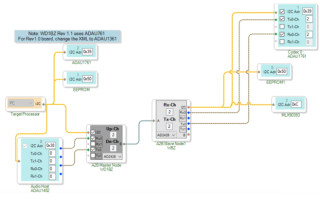
Here is the schematic created for the Single-master, Single slave with I2c device, and audio functionality with EVM EVAL-AD2428WD1BZ and EVAL-AD2428WB1BZ. The Audio host at master and slave configuration files(.xml) have been added into peripheral properties to configure the audio transfer from slave line-in to Master Line-out.

Figure 3: A2B Single Master Single Slave Schematic
As shown in figure 3, A2B Master node, Audio Host and I2c EEPROM devices are connected to the target processor (STM32) using I2c bus. A2B Master Node is connected to A2B Slave node, which contains I2c peripheral devices. All I2c devices have defined specified addresses which is used by A2B stack to access that device.
The schematic requires to be validated using PC and sigma studio before exporting to the .c file. This creates the bus configuration source file, which contains the details of each node, master, and slave I2c buses and peripheral devices node addresses to communicate. Place the bus configuration file to a2b_app/src directory. A2B stack parses this file and gets the parameters for all nodes, using this A2B stack runs the network discovery. A2B stack passes the discovery phase if node sequences, and properties defined in schematic matches with actual hardware connection.
The I2c device address defined in the into schematic is used to communicate to that device. Once these implementations are done, the A2B stack can discover and configure a connected A2B network.
3. Application Code Development
The last implementation required is application implementation. A2B stack provides three callback functions registered with stack, which can be used for important network activities. These can be re-implemented based on the end application design requirements for event handling.
- Discovery completion callback function:
a2b_msgRtrSendRequest(msg, A2B_NODEADDR_MASTER, a2bapp_onDiscoveryComplete);
- Power/Line callback function:
pApp_Info->notifyPowerFault = a2b_msgRtrRegisterNotify(pApp_Info->ctx, A2B_MSGNOTIFY_POWER_FAULT, a2bapp_onPowerFault, pApp_Info, A2B_NULL).
- Interrupt callback function:
pApp_Info->notifyInterrupt = a2b_msgRtrRegisterNotify(pApp_Info->ctx,
A2B_MSGNOTIFY_INTERRUPT, a2bapp_onInterrupt, pApp_Info, A2B_NULL).
For this STM32 based A2B implementation, the sample existing callback implementation has not been modified. The a2b_setup is called at the start of the application, for A2B discovering and configuration. Once the A2B Setup returns the success, the A2B network is ready to transfer the audio from slave to master over A2B.
The A2B PAL I2c Functions are used to communicate to the I2c device connected at A2B Slave. Here is the sample of the code which communicates with A2B slave I2c device to get the motion data.

Along with this application requires to have a continuous loop for monitoring any of the fault occurred over A2B and providing the tick to a2b stack. The continuous tick keeps the A2B stack activated.

Hardware Interfaces:
EVAL AD2428 master node is connected to STM32 using I2c line. Eval AD2428WD1BZ board contains P1 connector to communicate between AD2428 transceiver with target platform. Connect I2c and reset lines between Eval board with STM32 I2c bus as shown in below diagram.

Figure 4: AD2428WD1DZ Sigma Studio to STM32 Connection
For this project, evaluation boards, STM32 Microcontroller and I2c Peripheral devices are connected as shown below diagram.

Figure 5: A2B-STM32 Connections
Conclusion:
In this article, we have discussed how we can use Automotive Audio Bus or A2B for audio transfer along with I2c device access over the STM32 controller platform. This project was created using Analog Devices, Inc evaluation boards. The details provided can help in creating actual products (audio products and others) around A2B and STM32 microcontrollers technology. A2B and Automotive Audio Bus are a registered trademark of Analog Devices, Inc. ADI’s main A2B webpage provide links to part information, ADI tools, and design information. For more information visit here.
eInfochips has in-depth expertise in the areas of device engineering and embedded systems development. eInfochips as an aerospace solutions provider offers customized in-flight infotainment solutions for the aerospace industry. Know more about our solutions for the aerospace industry.
References:
- https://wiki.analog.com/resources/tools-software/sigmastudio/usingsigmastudio
- AE_09_A2B_SigmaStudio_UserGuide.pdf
- AE_09_A2B_Stack_UserGuide.pdf
Bhumi Shah is a Technical Lead at eInfochips - An Arrow Company. She has more than 12 years of experience working on Embedded software development, verification and validation for multiple domains like Avionics, Networking, and Multi-Media. She holds a bachelor’s degree in Electronics & Communications from Gujarat University, India.

Bhumi Shah is a Technical Lead at eInfochips - An Arrow Company. She has more than 12 years of experience working on Embedded software development, verification and validation for multiple domains like Avionics, Networking, and Multi-Media. She holds a bachelor’s degree in Electronics & Communications from Gujarat University, India.