DC Motor Controllers: Brushed vs Brushless
August 31, 2021
Story
DC motor controllers are special electronic devices used to manage the operation of direct current motors. Do all DC motors need a controller? Not at all. Let’s figure out which DC motors use it and for what purposes.
In this article, we’ll consider two types of DC motors: a brushed DC (BDC) and a brushless DC (BLDC) motor. Both types use a controller that can start and stop the motor, regulate its speed and torque, and perform other functions. However, a controller is much more important for a BLDC motor as it is part of the commutation process which is critical to all motors powered by direct current. Here, you’ll learn more about the differences between brushed and brushless DC motors and their control systems.
An Overview of BDC and BLDC Motors and Controllers
To create the rotation of a DC motor, you need to switch or commutate the current applied to the motor and change the polarity of the magnetic field generated around the wound component of the motor.
In a BDC motor, the current flows through the windings of the rotor, while its stator can have either windings (series, shunt, compound BDC motors) or permanent magnets (permanent magnet BDC motor). The motor’s motion depends on the interaction of the magnetic fields generated around these two components. Thus, their oppositely charged fields attract and similarly charged fields repel each other.
Another key element of a BDC motor is the commutator that switches the polarity of the current and applies it to the rotor’s windings through the electrical contacts called brushes.

A BLDC motor also has a rotor and a stator, but unlike in a brushed motor, the current flows through the windings of the stator. The rotor that’s made of permanent magnets can be located either on the inside of the motor (inrunner BLDC motor) or on the outside (outrunner BLDC motor).
A BLDC motor doesn’t have mechanical parts such as a commutator or brushes, as here the commutation is an electronic process driven by a controller. By estimating the position of the rotor, the controller decides when to switch the current and which stator’s winding to energize. Thus, a controller is critical for the operation of a brushless motor.

Apart from this, BDC and BLDC motor controllers have the same functionality; they can engage in starting and braking a motor, reversing its rotation, and controlling both its speed and torque.
Application Features of Brushed and Brushless DC Motors
Both brushed and brushless DC motors have their own strengths and weaknesses that define their application areas. For example, a BLDC motor has a smaller and more lightweight construction that has no effect on its efficiency. That is why it has wide use in portable electronics and wireless devices of different sizes.
A BLDC motor controller switches current at a higher frequency when compared to a mechanical commutator. This allows the motor to maintain a high torque and run smoothly at both low and high speeds. Reliability and low maintenance are also among the strong points of a BLDC motor. So the scope of its application may include its use in the following:
- electric cars;
- unmanned aerial vehicles (UAVs);
- home electronics;
- industrial robots.
BDC motors have given way to their brushless counterparts in some applications. In fact, the mechanical commutation is less efficient and often leads to power losses. The sparks created during the current switching can cause a high level of electronic noise. In addition, brushes need regular maintenance and/or replacement.
Despite all of these drawbacks, BDC motors are still popular in low-power systems and applications that favor simplicity and cost-efficiency. They can be found in remote-controlled toys, simple home, industrial, and automotive appliances.
A BDC motor controller has a simpler design and implementation than a BLDC controller as there are no complex electronics and algorithms that make it a more attractive choice in some cases. So, let’s see what it takes to build each of these devices.
Building a BDC Motor Controller
Before building a DC motor controller, you should specify your technical requirements and choose a particular type of device. The controller’s characteristics include, but are not limited to:
- Power regulation
To regulate the speed or torque, a BDC controller increases or decreases the power supplied to the motor. A linear voltage regulator allows a controller to apply constant voltage during the entire working cycle of the motor.
This type of regulation is generally no longer in use in modern controllers as they mostly rely on a switching voltage regulator with pulse-width modulation (PWM). This method allows the controller to change the level of voltage and current by supplying it in pulses.
- Type of control
Simple systems use a DC motor controller to regulate the motor’s operation without getting any feedback. Thus, an open-loop controller cannot correct the parameters of the motor.
The opposite is applied to a closed-loop DC motor controller that can receive feedback from the motor and regulate its speed, rotational direction, and other parameters as required.
Other characteristics of a DC motor controller include the power and operating voltage of a motor. To ensure the reliability of the motor and its controller, you should be aware of the power source and the level of voltage necessary for the motor to operate properly. Thus, you can choose between motor controllers of low and high voltage and power.
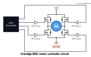
As mentioned above, most brushed motors use PWM controllers. Such devices have an H-bridge circuit with two high-side and two low-side switches. For example, when the motor needs to gain speed, the controller increases a duty cycle (the ratio of the pulse to the pulse period). Modified PWM signals arrive at the gate drivers that open the transistors for a longer time and let more current in.

To rotate a BDC motor in one direction, the controller opens the H-bridge switches on the diagonal. The switching process always comes with some delays, so when reversing the rotation, all four transistors may be turned on. To prevent the motor from experiencing voltage and current leakages, you can add dead time that allows the controller to keep all transistors closed and open in turns.
To implement a closed-loop control circuit, you can use a position sensor. The controller will read the signals sent by the sensor and react accordingly. In one of our projects, we created a programmable DC motor controller that could work as both a closed-loop and open-loop system. To receive feedback from the motor, we added a rotary encoder for monitoring the motor’s condition.
Building a DC motor controller with feedback, you should be mindful of the capabilities of your microcontroller. The MCU should:
- cover the frequency range of the sensor’s signals;
- have the necessary signal processing rate;
- have sufficient RAM and Flash capacity;
- have an analog-to-digital converter (ADC) if the sensor is analog.
Building a BLDC Motor Controller
A BLDC motor controller switches the current using transistors of a half-H bridge circuit. The number of transistors depends on the number of phases or windings energized by the controller. A 3 phase brushless DC motor controller (one of the most common configurations) requires three half-H bridges, that is one high-side and one low-side switch for each phase.

Upon receiving MCU signals, the gate drivers open the transistors and supply the current to the stator’s windings. To switch between the phases, the controller needs to know the position of the rotor. There are two ways to detect it:
- install a position sensor and use its measurements;
- sense back electromotive force (back EMF) that arises in the stator’s windings together with the rotor’s motion.
The first method is simpler, but the sensors need regular maintenance (for example, optical sensors are prone to dust). In addition, you’ll have to add more wires which complicates the motor’s construction. The second solution is simpler at the hardware level, but it might require complex algorithm development. The important thing is that you can sense back EMF only when the rotor moves.
From our experience, the positioning accuracy increases when the sensors are used together with the back EMF sensing method.
Once the rotor’s position is detected, a BLDC motor controller switches the current and applies it to different phases as either a trapezoidal or sinusoidal waveform.
The trapezoidal commutation has a simpler implementation, however, it may cause torque ripple at low speeds and becomes smooth only when the motor picks up speed. A sinusoidal DC brushless motor controller mostly relies on pulse-width modulation to create sine waves. This method provides smooth switching at low speeds, but it is harder to build sine waves at high frequencies.
Most brushless motors have closed-loop controllers that use position sensors and special algorithms to receive feedback from the motor and respond to it. One of such algorithms is a proportional-integral-derivative (PID) algorithm that is widely used in feedback systems of both BLDC and BDC motor controllers.
A PID algorithm processes the current motor’s parameters and compares them with the reference values. Based on this data, it adjusts the frequency of the output signals, and the controller regulates the speed accordingly.
Conclusion
Direct current motors are in great demand in various industries. Being interchangeable in some applications, BDC and BLDC motors still have their niches. For example, the low cost and simplicity of a brushed motor make it a suitable choice for electronic appliances used on a daily basis. Electronically commutated BLDC motors provide reliability and efficient speed control in applications of varying power.
DC motor controls have different working principles and design features. To learn more about them, you can check our articles on brushed and brushless motor controllers.
As an embedded hardware and software development company, Integra Sources provides electronic design and programming services for a variety of electronics, including motor controls, power converters, charging stations, battery management systems, and many other devices. Find out more about us and our services here.

Co-founder and CTO at Integra Sources. Earned Ph.D. in Physics and Mathematics at Altai State University.