Camera slider controls upgrade yields valuable prototyping lessons
April 11, 2018
Story

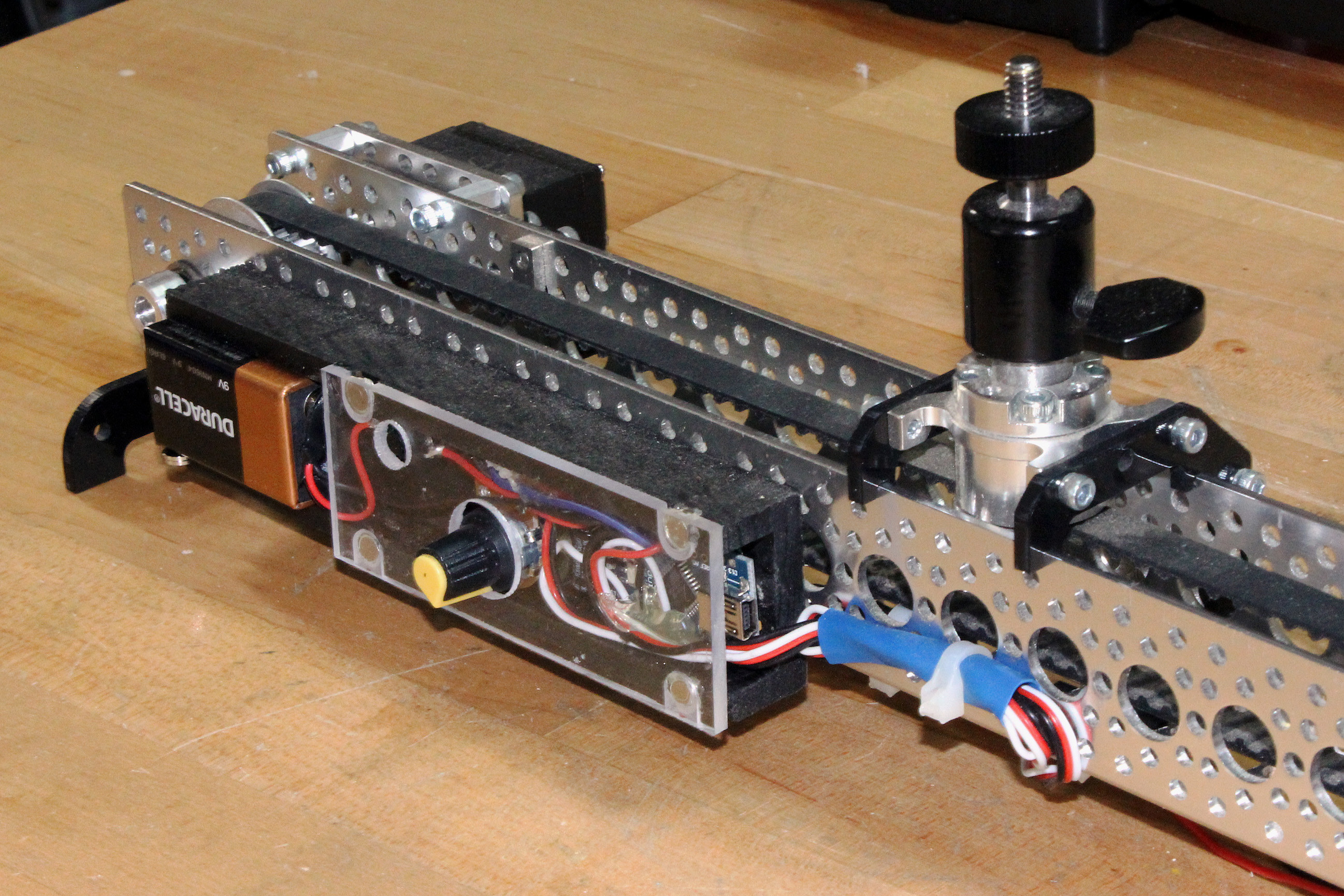
One thing I?ve enjoyed integrating into videos are physically panning shots, taken with a slider. My setup worked well, but the controls were extremely poor.
For several years, I’ve been making YouTube videos. While they were quite poor at first, and perhaps only better than average now, as I put myself out there you can see the incremental improvements adding up year after year. One thing I’ve enjoyed integrating into videos are physically panning shots, taken with a slider. My setup worked well, but the controls were extremely poor. In fact, when I took on this project, I was going so far as to physically hold the wires on my drive motor, forming a sort of human H-bridge circuit. Something had to be done, and I finally replaced things with a continuous rotation “servo” along with an Arduino Nano for control. Along the way I implemented a few tricks that are helpful whether you’re building a slider or some other robotic prototype.
Extra power from Arduino Nano
You can make a reasonable argument that you shouldn’t run servos off of an Arduino Nano’s power supply. Putting that aside, if space is at a premium, and you don’t mind potentially damaging your $2 Nano clone, then one solution that I used successfully here is to put a 10 microfarad capacitor between the ground and +5V pin. This helps even out power spikes when the motor starts up. As a huge bonus, I left the legs attached and bent them outwards, making a very convenient place to solder the several ground and +5V components that I used. The lack of physical pins can be a huge problem in this situation, and this solution worked out nicely.
Fritzing is amazing and free for design illustration tool
Fritzing is a PCB design package that lets you start with illustrated components to make the process user-friendly. Even if you don’t intend to use it for actual PCB design, a very useful side benefit of this program is that it allows you to draw out circuits, complete with colored wires and available components—batteries, dev boards, buttons, resistors, etc. This is great for getting your point across if a normal schematic doesn’t quite fit into your presentation.
Pulldown resistors or built-in pullup resistors
When an Arduino pin is set to input, if there’s nothing connected it can float from high to low, giving you a very unreliable reading. The two switches on my slider were definitely exhibiting this behavior when they were off, so I hooked in two separate 20k ohm resistors to go from the corresponding Arduino pins to ground, forcing them low when not engaged. While this worked out well, an easier option would be to pull the pins high via using the built-in pullup resistors in the Arduino’s ATmega328 chip via software as outlined here.
Wood tapping and magnets
A huge part of this build was making the controls fit into an easily portable enclosure. In order to attach it to the slider via machine screws, I used a technique where I drilled and tapped the wooden enclosure, using super glue before tapping to reinforce the wood. I’ve used a similar technique with 3D-printed parts, though without glue in that case.
Another trick I used to make an excellent enclosure was the use of rare-earth magnets to hold both the 9V batter in place as well as the cover. These magnets form an expedient way to attach things, though as I’d find out later, the hot glue that I used tends to detach. Using epoxy or simply scratching the glued surface may help hold the magnets better.
More ideas
The former servo motor that I used worked adequately in this application, but if the software wasn’t setup at exactly the correct value to stop it, it would tend to drift after hitting a switch. It could only be slowed down so much before becoming unreliable. More control could be gained with a stepper motor, or perhaps even one of the other options listed here. I could also add a few more axes to control pan and tilt settings coordinated with the slider itself, automatic camera control, or any number of advanced options. I’m happy with how things turned out, but as with most project like this, it’s entirely possible that it will never really be done!