Designing Reliable 2- and 3-Wheel Electric Vehicles to Improve Air Quality and Reduce Environmental Impact
July 22, 2021
Blog

Robust design of circuit protection, power control, and temperature management circuitry is key to long-term durability and safety.
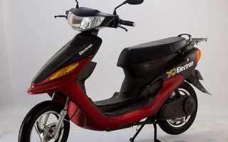
The development of electric 2- and 3-wheel vehicles is just as important as 4-wheel and larger electric vehicles for combatting pollution and mitigating climate change. The large quantity of combustion-based 2- and 3-wheel vehicles have fewer combustion controls than automobiles and trucks and generate a significant amount of pollution. Designers of 2-and 3-wheel electric vehicles (EVs) face the same significant challenges as designers of 4-wheel and higher EVs. Those challenges include maximizing mileage between battery charges, high vehicle reliability, and vehicle safety.
Market demands for more mileage between battery charges necessitate reducing the power draw of the circuitry to optimize efficiency. In addition, market requirements for high reliability and safety ensure that designers develop circuits that are robust to transients such as lightning and electrostatic discharge (ESD).
Figure 1 provides examples of the sub-systems of a 2-wheel scooter and the protection, control, and sensing components that enhance reliability and efficiency. This article will concentrate on recommendations for making three sub-systems in 2- and 3-wheel EVs robust and efficient. The three sub-systems are the Battery Management System (BMS), the Engine Control Unit (ECU), and the On-Board Charger. The focus will be on both protection and sensing components to protect these circuits from damage due to overloads and transients, and control components to minimize power draw and maximize battery life.

Figure 1. 2-wheel EV sub-systems and their circuit protection, control, and sensing components
The Battery Management System (BMS)
The BMS manages the battery output and keeps the individual battery cells balanced. The BMS also monitors and controls power from the charger and protects the batteries. Included in a typical BMS are the battery monitoring and management circuitry, battery cell protection circuitry, and a communication interface. Figure 2 shows the block diagram of the BMS.

Figure 2. Battery Management System block diagram showing the circuits where the recommended protection, control, and sensing components are located
Battery Disconnect Unit
High energy battery packs may contain a Battery Disconnect Unit. This essential system provides pre-charge connection, connection to, and disconnection from the load, fusing, and current sensing. If an overload condition is detected, this circuit opens and isolates the battery pack from the load. Since this circuit controls the high power to the motors, it is recommended that the circuit be fused with a time-delay fuse that can withstand high inrush currents from the motors and the motor starters. Ensure that the fuse has a high resistance when it has tripped so that the overload current is completely interrupted. Look for a fuse that specifies at least 1 MΩ of open circuit resistance. The selected fuse should be a UL- or CSA- component compliant with either the ISO 8820 or the AEC-Q specification. Fuses with these characteristics are available with current ratings up to 500 A; and, pre-approved components speed up and reduce the cost of standards certification.
A transient voltage suppressor (TVS) diode is recommended to suppress transient voltages such as load dumps, ESD, and lightning from damaging downstream sensitive electronic circuits. TVS diodes can:
- Safely absorb an ESD strike a high as 30 kV that arrives either through the air or via direct human contact
- Safely absorb up to 600 W of peak pulse power (higher-power versions are available if needed)
- Quickly respond to a transient in under 1 ns.
Versions of TVS diodes can be either bi-directional or uni-directional. If the diode could potentially encounter a reversed battery condition, use a bi-directional diode. For automotive grade components, look for AEC-Q qualified TVS diodes certified to the AEC-Q101 discrete semiconductors standard.
Designers should protect the lithium-ion battery pack with fuses for the individual battery cells (on the Sense Lines) to prevent damage to the pack from a cell or a group of cells having a short circuit failure. Select compact, fast-acting fuses to protect the individual battery cells. Choose fuses that:
- Have a current interrupting rating of at least 50 A
- Can withstand an inrush current but will open within seconds if the battery current exceeds 250% of the fuse’s nominal rating
- Can operate in an environment between -55° C and +150° C and are AEC-Q compliant
- Have surface-mount packages for consumption of minimal PC board (PCB) space.
To disconnect the battery pack from the load during normal operation, during charging, or when a problem is detected, consider a high current/high voltage DC contactor relay. These types of relays can carry as much as 250 A with a 900 V rating. Consider using an IP67 sealed, gas-filled version of the relay to mitigate the risk of arcing. Look for units that save energy by operating in a pulse width modulation mode.
Cell Protection Module
The Cell Protection Module protects the battery pack from overheating. For this module, use a negative temperature coefficient (NTC) sensor thermally coupled to the battery cells to monitor battery temperature. A hermetically sealed NTC sensor in a glass package is recommended. This provides long-term stability and reliability even under severe environmental conditions.
I/O Communication Interface
The I/O Communication Interface transmits the status of the batteries to the master controlling processor. For this circuit block, it is necessary to protect the interface’s data lines from ESD, according to ISO 10605, and from other voltage transients with a TVS diode array. Look for specifications that:
- Indicate compliance with IEC 61000-4-2 and provide at least 25 kV of ESD protection from through-the-air strikes and from direct human contact
- Provides a low clamping voltage, or has low dynamic resistance value
- Draws a low current, such as under 100 nA during normal operating conditions
- Documents AEC-Q101 qualification.
Figure 3 shows a type of TVS diode array. In this case, one space-saving package protects two data lines (e.g., for CAN bus).

Figure 3. 2-Port TVS diode array for protection of data lines from damaging voltage transients of either polarity
Battery Swapping Circuit
The Battery Swapping circuit block switches between primary and secondary battery packs. Having two battery packs extends travel distance between charges. Use a switch with a high open circuit resistance to avoid unintended current between the two battery packs. A reed switch can meet this requirement. Reed switches can have an insulation resistance on the order of 1012 Ω. Look for a reed switch with a contact rating up to 200 V, a switching current rating of at least 0.5 A, and a power handling capacity of at least 10 W.
Leakage Current Circuit
High-end motorcycles and scooters monitor the leakage current to the vehicle chassis. If the leakage current exceeds a pre-determined limit, a relay closes to send a signal to the battery management circuit. Consider an optically coupled solid state relay for this purpose. The solid-state relay should have:
- A low on-resistance under 10 Ω
- Low leakage current of under 50 nA
- Voltage and current ratings up to 100 V and 150 mA, respectively
- Input-output isolation of at least 1500 Vrms.
These requirements will ensure a robust relay that sufficiently isolates the control signal from the Battery Management circuit block when the leakage current is within limits.
With this small quantity of protection, control, and sensing components, the Battery Management System will be a robust and reliable sub-system of the electric vehicle.
The Engine Control Unit
The Engine Control Unit (ECU) is the primary processing and control unit of the vehicle. The ECU controls the motor drive circuitry and processes data, such as the status of the battery pack, so the driver is aware of the condition of the battery pack. Figure 4 shows the circuits that comprise the ECU.

Figure 4. Engine Control Unit/Motor Drive block diagram showing the circuits where the recommended protection, control, and sensing components are located
Auxiliary Power Control Unit
The Auxiliary Power Circuit acts as a lower-voltage power supply for the processors and other circuit components that control the action of the switching FETs and the motor. Consider using both a high current-rated fuse to protect this system from overload currents and a fast-acting fuse to protect individual circuits from overloads. Consider using the same fuses suggested for the Battery Disconnect Unit in the Battery Management System. As an alternative to the one-time use fuses for component-level protection, consider a polymeric positive temperature coefficient (PPTC) resettable fuse which resets to normal operation after a fault is cleared. They are especially useful when the assembly or user errors are expected to be the primary source of potential, temporary faults. Look for PPTC resettable fuses with:
- Current ratings up to 15 A and voltage ratings around 60 VDC
- Surface-mount packages for space-savings and automated PCB insertion.
Protect the Auxiliary Power unit from ESD and voltage transients with a TVS diode. Consider using the TVS diode recommended for protecting the BMS Battery Disconnect Unit.
Reverse Polarity Power Bridge Protection
The Reverse Polarity Power Bridge Protection circuit protects the motor drive circuit from the battery being incorrectly connected to the vehicle circuitry. For this reverse polarity protection, consider using a Schottky diode (which can also be used for rectification in the DC-DC converter circuit). Schottky diodes offer low forward voltage drop to reduce energy loss and enable increased converter efficiency by allowing higher frequency operation of the converter. In addition, higher frequency operation permits the use of smaller inductive components which save costs and PCB space. Given the usage of switching components (IGBT, MOSFET) in this circuit, it can be susceptible to high temperature failures. This failure manifests itself when a FET enters a resistive short circuit condition. To protect against this condition, a thermal protector is recommended to disconnect the circuit from the power source in the event an uncontrolled overheating condition occurs. Select a component that can interrupt up to 500 A.
Motor Drive Circuit
The Motor Drive Circuit contains the power output circuitry to drive the motor. For this circuit, consider MOSFETs or a MOSFET module for the power drive. Look for MOSFETs with:
- Low Rds(on) to minimize switching power losses
- High heat efficiency and fast dv/dt ratings to efficiently drive the motor load.
Use a gate driver to efficiently control the MOSFETs. Consider a dual output device for controlling a high-side, low-side MOSFET output configuration. Also, look for drivers with latchup protection and fast rise/fall times that exceed the MOSFET dv/dt times. Drivers are available that have rise and fall times under 10 ns.
Be sure to monitor the motor drive circuit for overheating by using a digital temperature indicator. An example of one with its resistance vs temperature curve is shown in Figure 5. This device, a polymer temperature indicator, can change its resistance by a factor of 108 when a temperature threshold is reached. The high resistance effectively creates a positive indication for the monitoring circuit, which can then turn off current to the motor. This component will reset when the temperature drops below the critical shut-off temperature, and power can be restored to the motor. Alternatively, you can select an NTC temperature sensor similar to the hermetically sealed glass sensor recommended for the BMS Cell Protection Module.

Figure 5. Resistance vs Temperature curve for the thermal protector and an example device
Motor
The key drive component, the motor, should be protected from overheating, excessive rotating speed, and a locked rotor. Two sensing components can address these conditions. An NTC temperature sensor identical to the one recommended to monitor the motor drive circuitry can monitor motor temperature and a Hall sensor/switch can monitor motor speed and rotor position. Hall sensors have versions that can output either voltage or current so you can select the output that best fits with your design. Look for a Hall sensor/switch with long switch life for maximum reliability. Hall sensor switches can achieve up to 20 billion switch operations.
I/O Communication Interface
The I/O Communication Interface enables the ECU to link with the vehicle sensing and control circuits as well as battery pack status lines. Protect the interface’s data lines from ESD and other electrical transients with a TVS diode array as recommended for the I/O Communication Interface in the BMS.
The ECU is the most critical system in the electric vehicle. Ensuring this system is properly protected is essential.
The On-Board Charger
The On-Board Charger converts AC power to DC power to provide the charge voltage and current for recharging the battery pack. Figure 7 shows the circuits that comprise the On-Board Charger and the protection, control, and sensing components recommended for the individual circuits.

Figure 6. On-Board Charger block diagram showing the circuits where the recommended protection, control, and sensing components are located
Input Protection, Rectifier, and Filter
Since this circuit is connected to the AC mains, the circuit is subject to the overcurrent conditions and voltage transients that can occur on AC mains’ lines. Use a time-delay fuse to interrupt current overloads. Make sure the fuse has a voltage rating in excess of the line voltage. It is recommended to select a UL- or CSA-component recognized fuse since the fuse connects to the AC line. For Automotive-level quality, consider selecting a fuse that is compliant with ISO 8820 or is AEC-qualified.
AC line transients can have significant energy, and components that can safely absorb this energy in these transients should be installed across the input of the circuit. For circuits where it is critical to minimize the clamping voltage during a voltage transient, a series combination of a metal oxide varistor (MOV) and a protection thyristor can be considered. Versions of MOVs can absorb peak currents as high as 10 kA with operating voltages over 800 VDC. They can also meet AEC-Q200 quality requirements for passive components. A bi-directional protection thyristor can absorb up to 3 kA of surge current with a response time in nanoseconds. Use versions of thyristors that are AEC-Q101 qualified. The series connection of the MOV and the thyristor can allow a lower clamping voltage compared to the use of a MOV by itself.
Power Factor Control Circuit
The Power Factor Control Circuit improves the efficiency of the charger by reducing the phase difference between the input voltage and current drawn from the power line. This maximizes real power delivered to the device and reduces apparent power that can have a higher peak current draw. For this circuit, the use of a low Rds(on) MOSFET with Rds(on) values under 500 mΩ to minimize switching and conduction losses is recommended. In addition, protect this circuit from self-induced voltage transients (Active Clamping) with high-voltage versions of the TVS diode recommended for BMS and ECU circuit blocks.
High-Frequency Converter and Clamp Circuit
The High-Frequency Converter and Clamp circuit convert the AC sinusoidal input into a high-frequency square waveform factor. Maximize circuit efficiency with MOSFETs for creating the square wave signal. Protect this circuit using the TVS diode recommended for the Power Factor Control circuit.
Output Rectification and Filter Circuit
The Output Rectification and Filter circuit create the DC charging voltage and current for the battery pack. Select a fast-recovery, high-frequency switching rectifier diode to minimize switching losses in the circuit. Select a rectifier diode with a high junction temperature in excess of 150° C for maximum reliability.
Output DC Protection Circuit
The Output DC Protection circuit connects the charging voltage and current to the battery pack. Use a fuse to protect the circuit from an overload due to a short in the battery pack or in downstream components or systems. Use the same type of fuse as recommended for the Input Protection circuit.
I/O Communication Interface
As with the BMS and the ECU, protect the I/O Communication Interface data ports from transients with the same type of TVS diode array used for the interfaces in the systems described earlier. Transient protection will help prevent catastrophic failure of the processors due to failure from a transient overload.
Input Protection and Filter
The Input Protection and Filter provide control of the charger output. This circuit should be protected with a TVS diode. Select a TVS diode with:
- 30 kV rating for ESD strikes either over the air or from direct human contact
- Transient surge protection up to 1 kA.
Look for an AEC-Q101 qualified component. When PCB space is tight, look for a space-saving surface-mount version.
Safety Standards for 2- and 3-Wheel EVs
Be aware of the national and international safety standards to which electric 2- and 3-wheel vehicles must comply. These standards are listed in Table 1. Save development time by addressing the standard requirements early in the design process. Ensure that the safety standards for the markets that will be targeted are included in the design definition.

Table 1. National and international safety standards applicable to 2- and 3-Wheel Electric Vehicles
Value in designing protected and efficient circuitry
By using the recommended protection, control, and sensing components, you can achieve the reliability the market demands. Your design will be resistant to overcurrent conditions and transient overloads. You can implement these protection measures and save design and development time by taking advantage of the manufacturer’s application expertise. The application engineers can help with component selection and provide guidance on complying with the applicable safety standards.
References:
- Circuit Protection Product Selection Guide, 2020, Littelfuse, Inc.
https://info.littelfuse.com/circuit-protection-product-selection-guide?utm_source=article&utm_medium=EmbeddedComputing&utm_id=EVI - Power Semiconductor Product Catalog, 2020-2021, Littelfuse, Inc.
https://info.littelfuse.com/power-semiconductor-product-catalog-lf?utm_source=article&utm_medium=EmbeddedComputing&utm_id=EVI - Using High Voltage TVS Diodes in IGBT Active Clamp Applications, 2020, Littelfuse, Inc.
https://www.littelfuse.com/~/media/electronics/application_notes/littelfuse_using_high_voltage_tvs_diodes_in_igbt_active_clamp_application_note.pdf.pdf


