That Simple Current-Sense Resistor Isn't Simple at All
January 22, 2019
Story

Sensing of current magnitude is critical in many applications and often done by measuring the voltage across a shunt resistor, but even this simple technique has subtleties and issues to resolve.
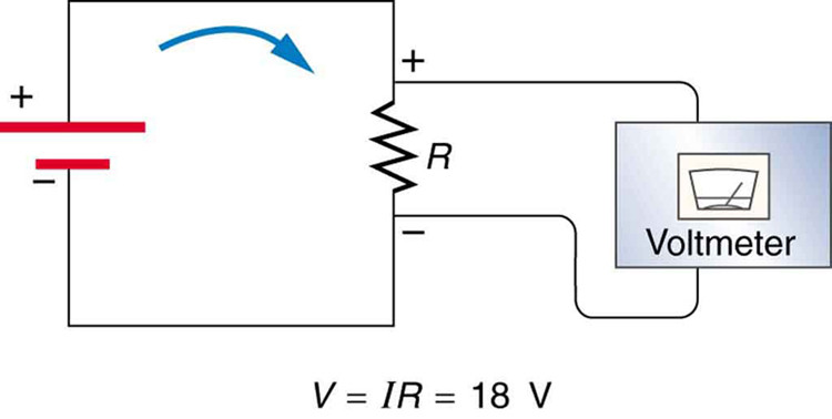
Measuring current to determine battery status or power consumed by a load such as a motor, lamp, or subsystem is a common circuit requirement. While there are various ways to do this, such as using a Hall-effect sensor or inductive current probe, the most popular way by far is to use a resistor of known value in series with the load, and measure the voltage across it (Figure 1). Then, a quick application of Ohm’s law (I = V/R) allows calculation of the current, as well as the power, if needed (Note that this resistor is often called a shunt resistor, although it does not “shunt” the current).
While the concept is simple and valid, the actual implementation raises three questions for which there are no single “right” answers. Instead, they are yet another case of the design dilemma of balancing various tradeoffs versus priorities and practicalities. Let’s look in brief at the three issues:
1) Where to place this resistor?
The obvious place is between the load and circuit common (often referred to as “ground” but this is often a misnomer, for various reasons; Figure 2). This low-side sensing is electrically the simplest approach, since the analog circuit across the resistor that measures its voltage can also be connected to common (ground).
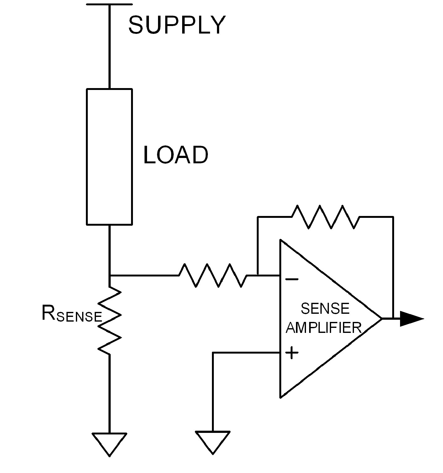
However, this arrangement has inherent problems. First, the load is now no longer grounded which leads to various performance and loop-stability issues. Even if those shortcomings were acceptable, in many practical cases the load is physically attached to ground (think of the starter motor in car, which is bolted to the car frame). The alternative is high-side sensing, where the resistor is between the supply rail and the load (Figure 3).
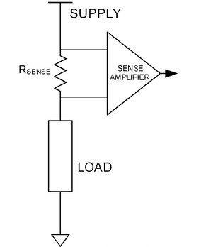
Figure 3. High-side sensing minimizes load and system issues, but brings new issues related to common-mode voltage and system integrity when measuring the voltage across the resistor (Image source: Stack Exchange Inc).
This eliminates the problem of the ungrounded load but means that the sensing circuit now is floating above ground, and a standard op amp cannot tolerate this topology. This brings us to the second question.
2) What can be used to sense the voltage across the resistor?
Since the sense resistor is no longer connected to ground (common), its amplifier must sense the voltage across its inputs with neither input being at ground reference. This requires a special amplifier called a differential amplifier (a standard, widely available device, which is an amplifier designed to measure the potential difference (a formal and indicative name for voltage) regardless of where that difference is with respect to ground – up to a certain voltage level, called the common mode voltage (SMV)).
Every difference amplifier has a maximum common-mode voltage it can tolerate while measuring the differential voltage; a typical value is 50 V. If the voltage drop across the load – seen as a voltage common to both ends of the resistor – is greater than maximum rating, the differential amplifier would saturate and be unable to make the voltage measurement, or possibly even be damaged.
If the common-mode voltage is too great for the differential amplifier, a more advanced approach is needed. One method is to use an isolation amplifier that is floating and has no galvanic connection to the system ground (Figure 4). Isolation amplifiers are available that can tolerate hundreds and even thousands of volts, but they are more costly than a basic differential amplifier.
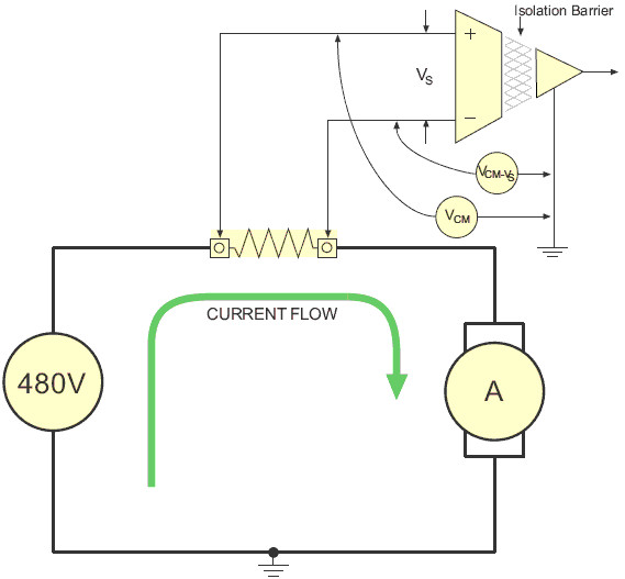
Figure 4. The isolation amplifier eliminates high-side sensing issues and may even be mandated for safety, but adds component cost (Image source: Datak Instruments).
They do, however, offer a major benefit compared to the differential amplifier. If the diff amp fails and shorts out internally, the full supply-rail voltage will appear at its output. This may burn out the connected circuitry and may even be hazardous to users (note that safety restrictions tend to come into force at around 60 V, depending on application, country, and standard to be met). In contrast, the isolation amplifier not only can withstand thousands of common-mode volts, but its design inherently prevents input-to-output shorts and thus protects the system and the user.
3) What value of current-sensing resistor to use?
Here we have an engineering dilemma that is easy to state and requires judgment as to the most acceptable answer. The voltage across the resistor is the parameter of interest, and is often being measured in the presence of noise from system clocks, motors, various loads, and even nearby systems. Therefore, to maximize the resolution, accuracy, and SNR of the voltage reading, a larger-value resistor is preferred.
But, on the other hand, the higher-value resistor has two negatives at a given current: first, it subtracts from the rail voltage and thus power that can delivered to load. Second, it also dissipates more power (I2R loss), which represents wasted power and induces self-heating. Even if the loss and inefficiency can be tolerated, the self-heating changes the resistance value itself due to its temperature coefficient of resistance (TCR). This TCR problem is more severe at higher current levels above a few amps. A basic low-cost resistor has a fairly high TCR, so the reading accuracy is skewed by the current flow itself. The alternative is to specify a special, low-TCR resistor fabricated for this purpose using unique formulations.
Assessing these tradeoffs in most designs, the optimum balance point between acceptable SNR versus excess dissipation and TCR-induced errors is to allow a maximum voltage drop across the sense resistor of about 100 mΩ, regardless of the rail voltage or current drain (there are exceptions, of course). Thus, a rail delivering up to 1 A to its load would use a 0.1 Ω (100 mΩ).
Vendors of currents-sense resistors do make them with such low values and even lower, such as the EBW series from TT Electronics (Figure 5), available from 25 to 500 μΩ, with 3W dissipation, 200 A capacity, and TCR below 200 ppm/°C. Even these extreme low-value resistors often can’t just be dropped into the circuit without consideration of their mounting and connection, as the typical contact resistance of a few mΩ between them and the connecting wires may be excessive. Therefore, sensor amplifier-lead attachment is critical, and Kelvin connections may be needed.
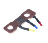
Figure 5. Current-sense resistors are usually in the mΩ and below range, with wattage rating matched to the current they handle; this EBW series resistor from TT Electronics may look like a simple strip of metal, but it is fabricated of specialty material to a precise µΩ value and includes provisions for Kelvin connections (Image source: TT Electronics).
This brief discussion proves, once again, that just because something has a simple concept behind it doesn’t means it will be simple to execute well. That’s the essence of the engineering challenge.